The problem of finding the resultant of a coplanar force system can be solved by means of a graphical solution. We shall illustrate the method first by means of a parallel coplanar force system.
Consider the system of three forces shown in Fig. 1a. We can find the magnitude and direction of the resultant by adding the forces by the polygon law, as in Fig. 1b, but this will not give us the location of the resultant. We can locate the resultant, however, by means of an extension of the graphical method which was developed in connection with this figure from Chapter: The Composition and Resolution of Force System .
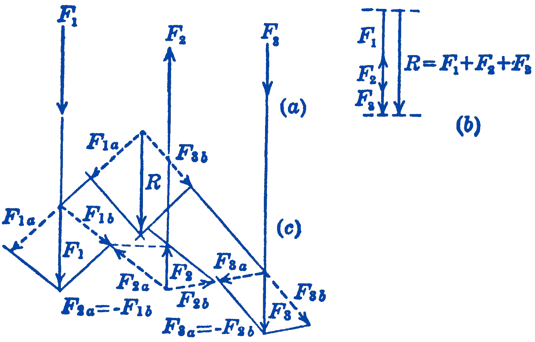
We first resolve the force \(F_{1}\) into two components, which may have any direction. These components are shown as \(F_{1 a}\) and \(F_{1 b}\) in Fig. 1c. We next resolve the force \(F_{2}\) into two components, one of which is equal in magnitude, opposite in direction, and colinear with the component \(F_{1 b}\) of the first force. Similarly, the third force is resolved into two components, one of which is equal in magnitude, opposite in direction, and colinear with the component \(F_{2 b}\) of the second force. We have thus replaced the original system of three parallel forces by a system of six non-parallel forces. Furthermore, four of these forces occur in equal and opposite pairs, so that they cancel out, and we have thus reduced the system of three parallel forces to a system of two non-parallel forces for which the resultant can be directly found. It will be seen that this method could be extended to include any number of forces, and that this system of any number of parallel forces will always be reduced to two forces.
The value of the above method lies in the fact that the various operations required for the solution can be combined into a simple graphical solution. In Fig. 2a are shown to scale three parallel forces. To identify the forces we shall use a new type of notation, for reasons that will become apparent as the graphical solution proceeds. Instead of lettering the forces, we letter the spaces between the forces. The first force in Fig. 2a would be called the force \(a b\), the second, the force \(b c\), and so on. This notation is called “Bow’s Notation” 1 and is widely used in the field of graphic statics. In Fig. 2b the force diagram is drawn to scale, and the forces are identified by means of the letters of Fig. 2a.
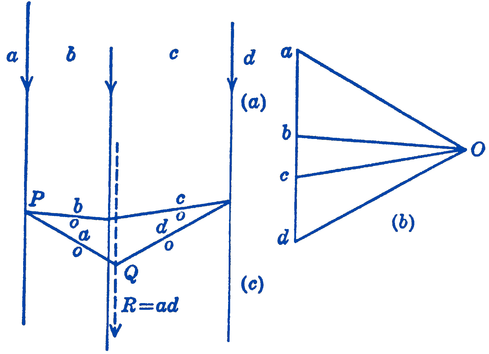
The magnitude of the resultant force ad can be directly measured from this diagram. To find the location of the resultant, we resolve the individual forces into components according to the following scheme. In Fig. 2b we pick a point \(O\) which we call the pole. The exact location of the pole is unimportant. We next draw lines from the points \(a, b\), etc., to the pole. These lines are called rays. Since these rays are located in the force diagram, they represent forces. It will be seen, for example, that the rays \(a o\) and \(o b\) represent two components of the force \(a b\), and the rays \(b o\) and oc are two components of the force \(b c\). Furthermore, the components ob and bo are equal and opposite, so that this construction gives us a mode of making the type of force resolution discussed in connection with Fig. 1 above.
We next transfer these force components to the diagram of Fig. 2c. Since each force is to be resolved into two components, some point on the line of action of each force will be intersected by two lines parallel to the rays which represent the two force components. We can begin the diagram by selecting any point \(P\) on the line of action of the force \(a b\), and by drawing through this point lines parallel to the rays \(ao\) and bo. Having drawn the line \(bo\) in Fig. 2c, the intersection of bo with the line of action of the force \(b c\) can be found, and through this point a line parallel to the ray co can be drawn. Each of the original forces is resolved into two components, all of which except two cancel out. The remaining two components \(ao\) and \(od\) then give the resultant force ad, and their point of intersection \(Q\) in Fig. 2c establishes the location of the resultant. Since we have already determined the magnitude of \(R\) from the force diagram of Fig. 2b, we do not need to show the force magnitudes in Fig. 2c which we use only to determine the location of the resultant.
The figure formed by the lines \(ao\), \(bo\), \(co\), and \(do\), in Fig. 2c is called the funicular or string diagram, or polygon, since it has the form which would be assumed by a flexible string loaded by the original forces.2 The lines in the funicular diagram which are parallel to the rays of the force diagram are called strings.
In the above example, we have taken a system which has a single force as a resultant. The method is also applicable if the resultant is a couple, as may be seen from the example of Fig. 3.
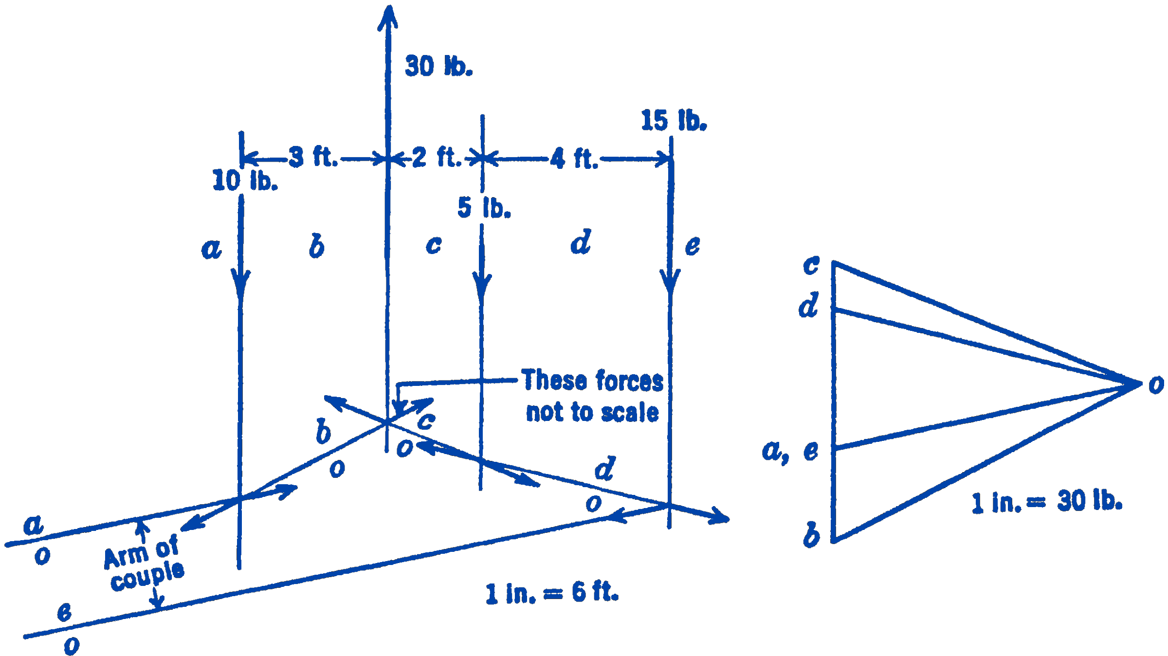
Four parallel forces having the magnitudes and positions shown are to be graphically added. From the force diagram of Fig. 3 it will be seen that the resultant force is zero, since the point \(e\) turns out to be coincident with the point \(a\). If we draw the funicular diagram we find that the first and last strings \(ao\) and \(e o\), the intersection of which should give the location of the resultant, do not intersect but are parallel, thus indicating that the resultant is a couple. The moment of the couple will be seen to be clockwise, or negative, and the magnitude of the couple will be equal to the magnitude of the component ao times the distance between the strings \(ao\) and \(eo\):
\[ M=-\left[(1.11 \text { in) })\left(30 \frac{\mathrm{lb}}{\mathrm{in}}\right)\right]\left[(0.35 \mathrm{in} .)\left(6 \frac{\mathrm{ft}}{\mathrm{in} .}\right)\right]=-70\ \mathrm{ft}\cdot\mathrm{lb} \]
which can for this problem be easily checked analytically.
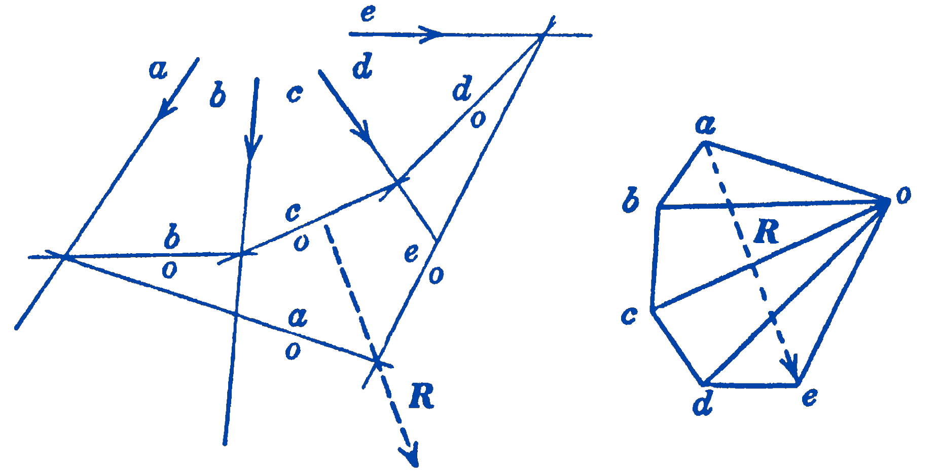
The foregoing method may also be used for non-parallel force systems as well as for parallel force systems, as may be seen from the example of Fig. 4.
6.6.1 PROBLEMS
1. Find the resultant of the system shown in Fig. 3 (see the following) by choosing a different position for the pole, and using the graphical method. Check this answer analytically.
2. A system of forces acts on a beam as shown in the diagram. Find the resultant of the system by the graphical method.
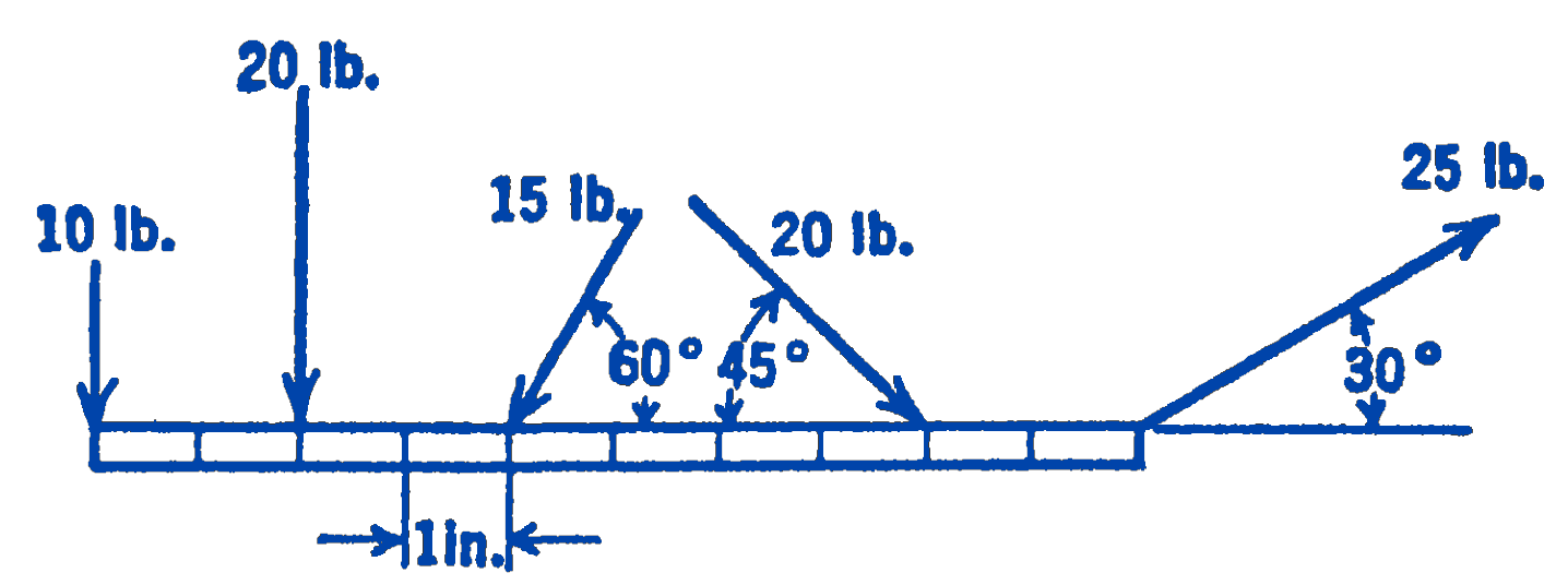
Answer
Magnitude of resultant \(=52.9 \ \mathrm{lb}\)
3. Find the resultant of the system of coplanar forces shown in the diagram by the graphical method.
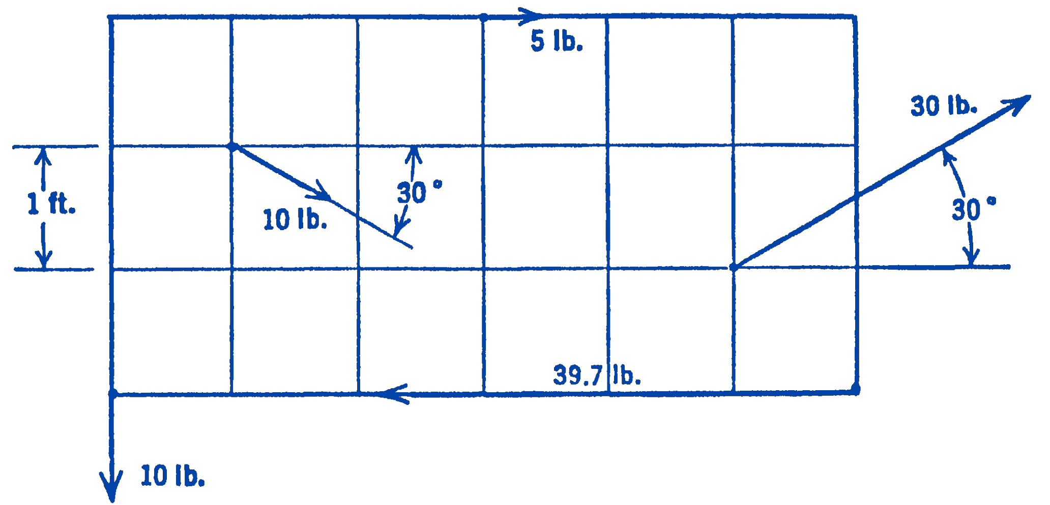
Answer
Magnitude of resultant \(=0\)