We have considered above two analytical methods of determining the forces acting in the members of a truss, the method of joints and the method of sections. In solving the equations which were written for the various concurrent force systems encountered in the method of joints, we used analytical methods. It would also be possible to use a graphical method, i.e., a graphically constructed force polygon, to find the forces involved in those concurrent force systems. The following example will show how this graphical method will apply to the solution of a typical truss problem. Suppose that we consider the same truss used above as an example of the analytical method and shown in Fig. 1. We further suppose that we have already solved for the reactions at the supports, either analytically, as in the above example, or graphically by means of a funicular diagram. We have thus the situation shown in Fig. 1a.
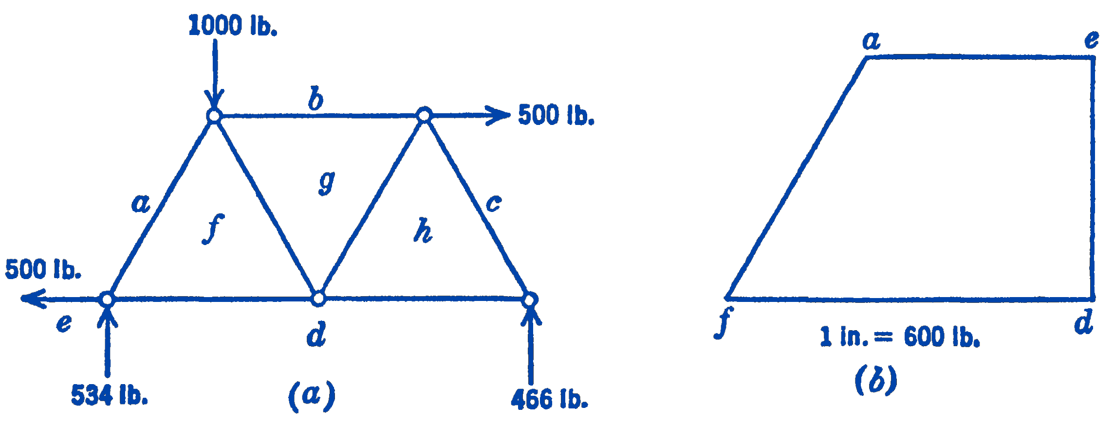
To identify the various forces, we use Bow’s notation, and letter the spaces between the forces in the space diagram, as in Fig. 1a. The force polygon for the left-hand joint is shown in Fig. 1b and will illustrate the use of Bow’s notation for this type of diagram. We adopt the convention of identifying the forces acting at any particular joint by reading the letters of Bow’s notation clockwise around the joint. By maintaining this consistency of direction, the signs of the forces can be automatically determined. For example, if we are referring to the left-hand joint, the force in the inclined member is (\(af\)), whereas for the upper left-hand joint the force in this same member is \((f a)\). Since these two forces should actually be equal and opposite, it will be seen that the above convention will lead to a consistent picture of the signs of the various forces. By reading the forces in the force polygon in their proper order, referred to any joint, it can be determined whether a particular member is in tension or compression. For example, in Fig. 1b, reading the letters clockwise, we see that the force (\(af\)) is directed toward the left-hand joint and is hence a compressive force, whereas the force \((f d)\) is directed away from the joint and is hence a tension force.
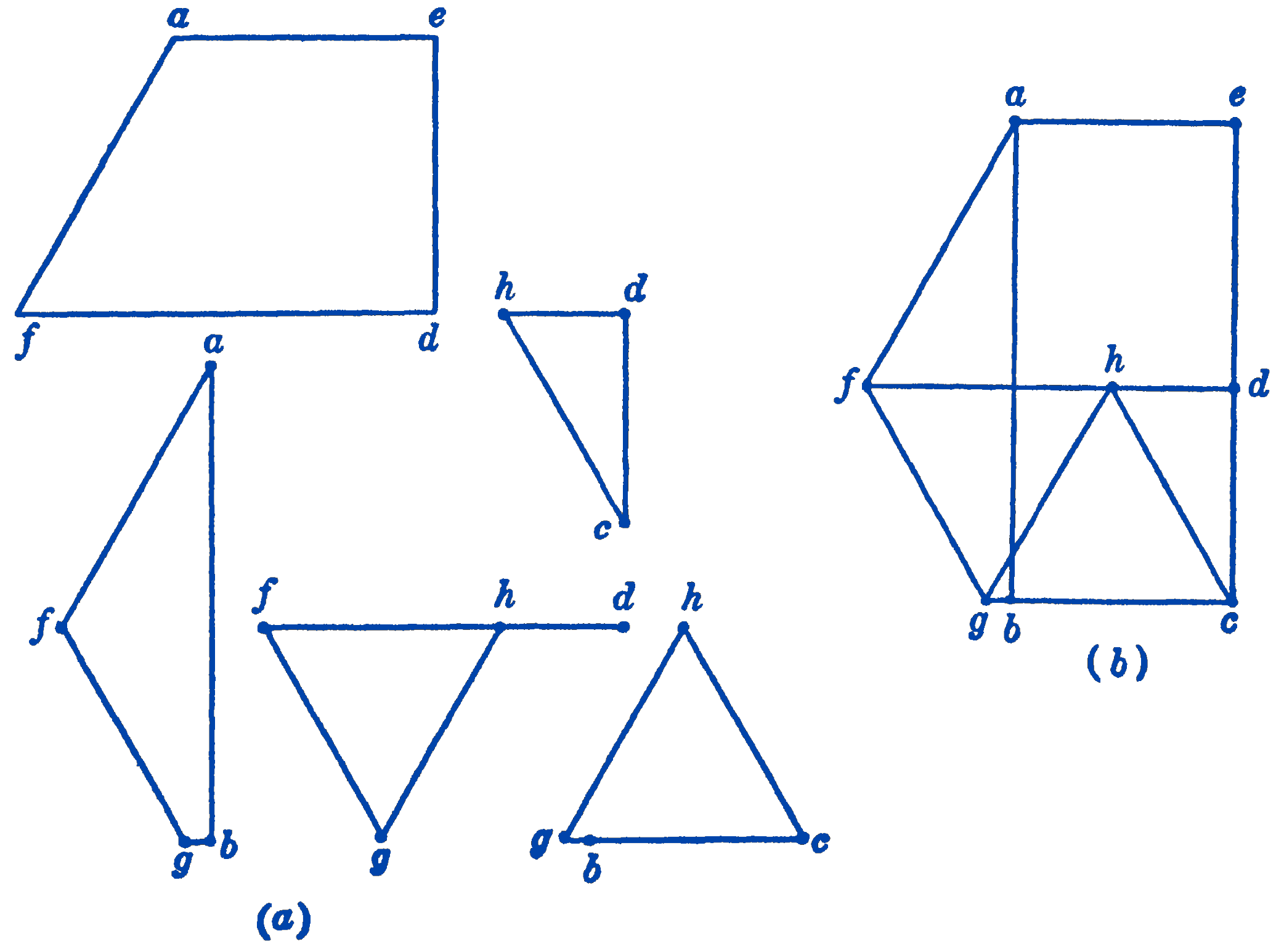
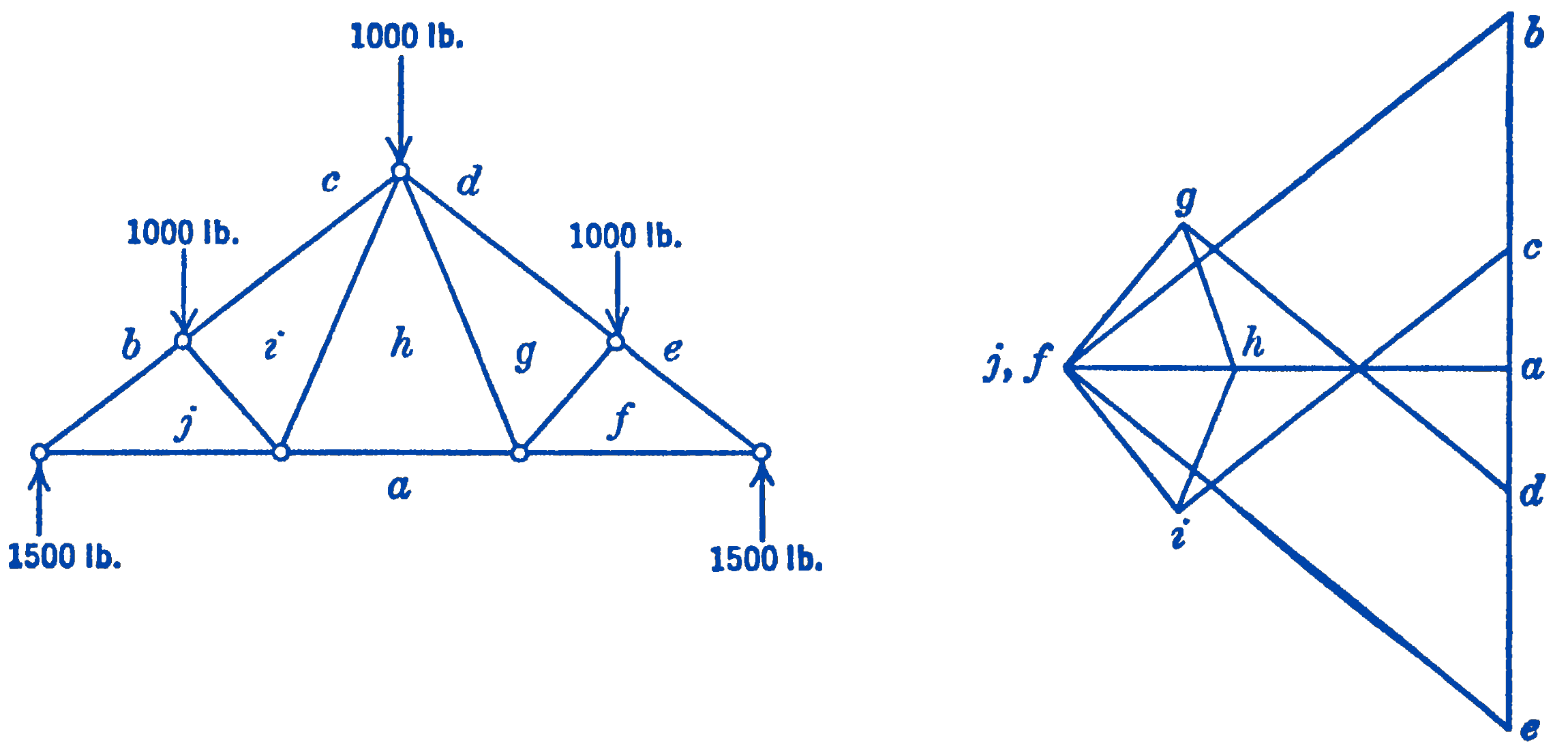
In Fig. 2a are shown the complete force diagrams for each of the joints of the truss shown in Fig. 1a. By examining these figures, it will be seen that many of the lines have been repeated from diagram to diagram, so that the construction could be considerably simplified if the diagrams were combined into one diagram for the whole truss, as shown in Fig. 2b. The combined force diagram obtained in this way is called the Maxwell-Cremona1 diagram and such diagrams are frequently used for the analysis of trusses. It will be evident that such a complete diagram could be drawn at once for any truss which the method of joints will solve. As a second example of the appearance of these Maxwell-Cremona diagrams, Fig. 3 may be consulted.
It should be noted that it is not necessary when constructing the Maxwell-Cremona diagram to draw the force polygon for each joint of the truss. The points of the diagram can all be located by starting from the known points and drawing lines parallel to the truss members through these known points. The intersection of these lines will determine the unknown points.
6.9.1 PROBLEMS
155. Find graphically the forces in the members of the truss shown in Problem 1 of Section: The Method of Sections by drawing the Maxwell-Cremona diagram. Compute analytically the reactions needed to start the diagram.
156. Same for Problem 2 of Section: The Method of Sections
157. Same for Problem 2 of Section: The Method of Sections
158. Same for Problem 6 of Section: The Method of Sections
- Maxwell, J. C. “On Reciprocal Figures and Diagrams of Forces,” Phil. Mag., Vol. XXVI, 1864, p. 250.↩︎