Another method of finding the forces in the members of a truss, the method of sections, is particularly useful for those problems in which the forces in only one or several members of a truss are to be computed. The method consists of drawing a free-body diagram of some portion of the truss, obtained by imagining that the members for which the forces are to be determined have been cut. This will usually result in a general coplanar force system for which three equations of equilibrium can be written.
Example. Referring to the truss solved above by the method of joints, find the force in the member \(C D\) by the method of sections (Fig. 1).
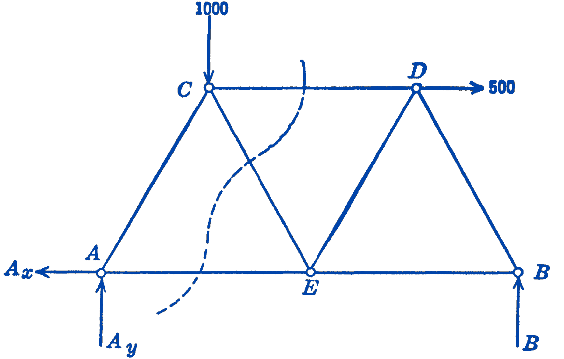
Solution. We imagine that we cut the three bars \(C D, C E\), and \(A E\), and we draw a free-body diagram (Fig. 2) of the left-hand portion of the truss:
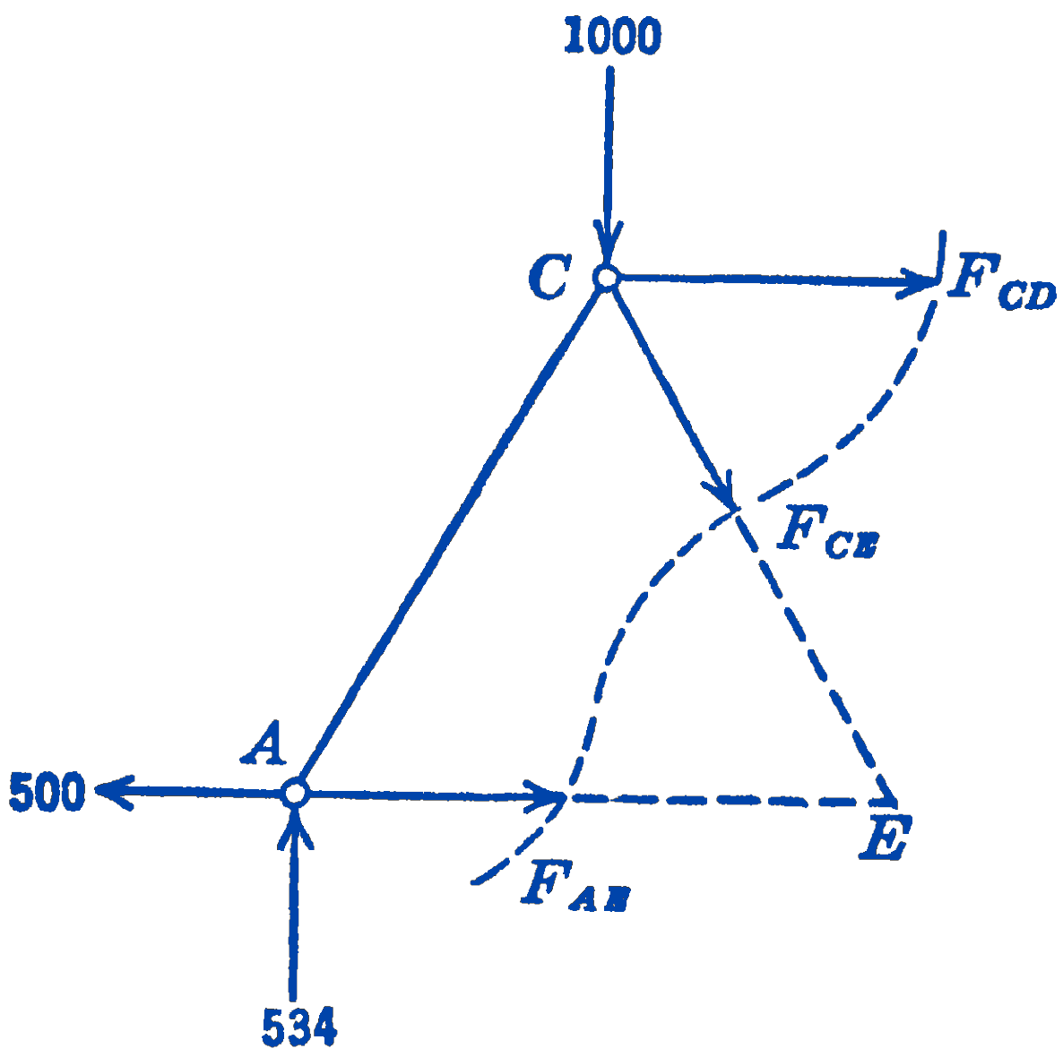
This is a general coplanar force system for which we can write three independent equations. If we determine \(A_{x}\) and \(A_{y}\) as in the previous solution by means of a free-body diagram of the whole truss, there will be left the three unknowns \(F_{C D}, F_{C E}\), and \(F_{AB}\), which can be found from the three equations.
If we require only the force \(F_{C D}\), we can find it directly from one moment equation by taking as a moment center the point \(E\), which is the point of intersection of the two unknown forces \(F_{C E}\) and \(F_{A E}\)
\[ \begin{aligned} \sum M_{E} & =0=-(534)(l)-\left(F_{C D}\right)\left(\frac{\sqrt{3}}{2} l\right)+(1000)\left(\frac{l}{2}\right) \\ F_{C D} & =\frac{500-534}{0.866}=-39\ \mathrm{lb} \text { (compression) } \end{aligned} \] which is seen to check the solution by the method of joints.
The same solution could be reached, of course, by taking the right-hand portion of the truss as the free-body diagram (Fig. 3): \[ \begin{aligned} \sum M_{B} & =0=(466)(l)+\left(F_{C D}\right)\left(\frac{\sqrt{3}}{2} l\right)-(500)\left(\frac{\sqrt{3}}{2} l\right) \\ F_{C D} & =\frac{(500)(0.866)-466}{0.866}=-39 \mathrm{lb} \text { (compression) } \end{aligned} \]
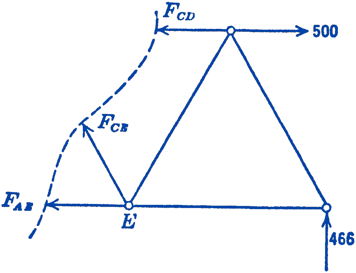
In this case the same amount of work is involved for each portion of the truss. In some problems, one portion will lead to simpler equations than the other and should thus be chosen.
It will be seen that the foregoing method of sections is very generally applicable. Most trusses are so arranged that a portion of the truss can be isolated by cutting three bars, and a moment equation can always be written about the point of intersection of two of the bars.
This leaves one equation and one unknown which can be solved directly. The advantage of this method over the method of joints is that the force in a member somewhere in the middle of a truss can be computed without first computing the forces in a number of other members. This advantage is, of course, of less importance if the forces in all of the members of the truss are to be determined. Even in this case it is usually worthwhile to solve for the force in one of the central members as a check on the numerical calculations.
There are certain types of statically determinate trusses which cannot be directly solved by the above methods. Consider, for example, the truss shown in Fig. 4.
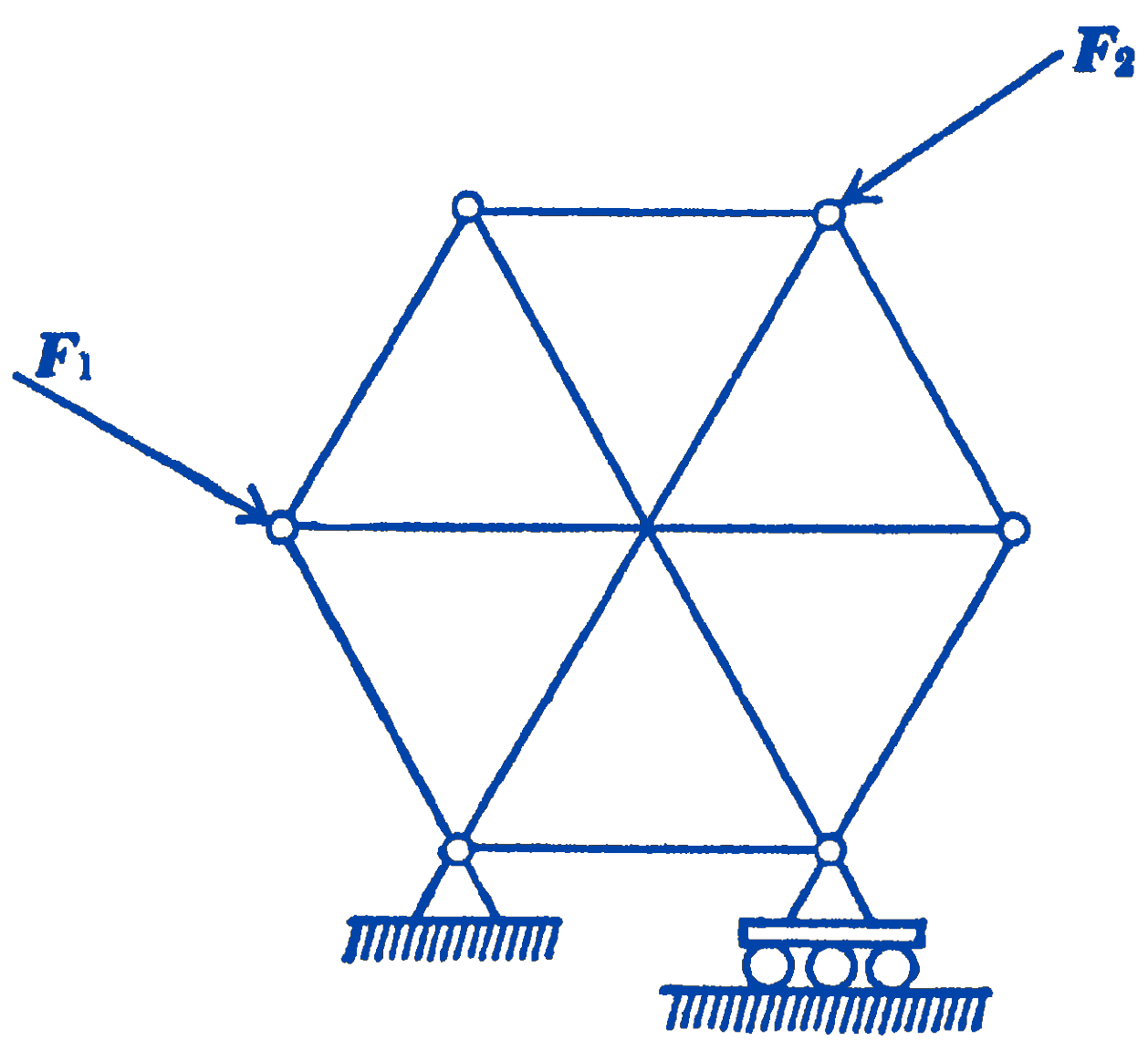
In this truss, the three members which intersect at the center are not connected there, but freely pass each other at that point. The number of joints in the truss is six, and the number of members is nine, so that the necessary condition for a statically determinate structure is satisfied. It will also be seen that the framework is rigid. If we try to apply the method of joints to this truss, however, we find that there is no joint with just two unknowns, so that we cannot start to unravel the solution. Similarly, with the method of sections, it will be found that the only sections which can be isolated by cutting three bars result in three concurrent unknown forces, for which no solution can be obtained. It is possible, however, to write all of the equations for all of the joints, and then to solve these equations simultaneously. This is, however, a very laborious procedure, which for larger trusses would hardly be a practical mode of calculation. Such trusses are called complex trusses, and special methods have been evolved for solving them. There is usually little reason to employ such a complex truss, since a simple truss could in most cases be designed which would be just as effective.
6.4.1 PROBLEMS
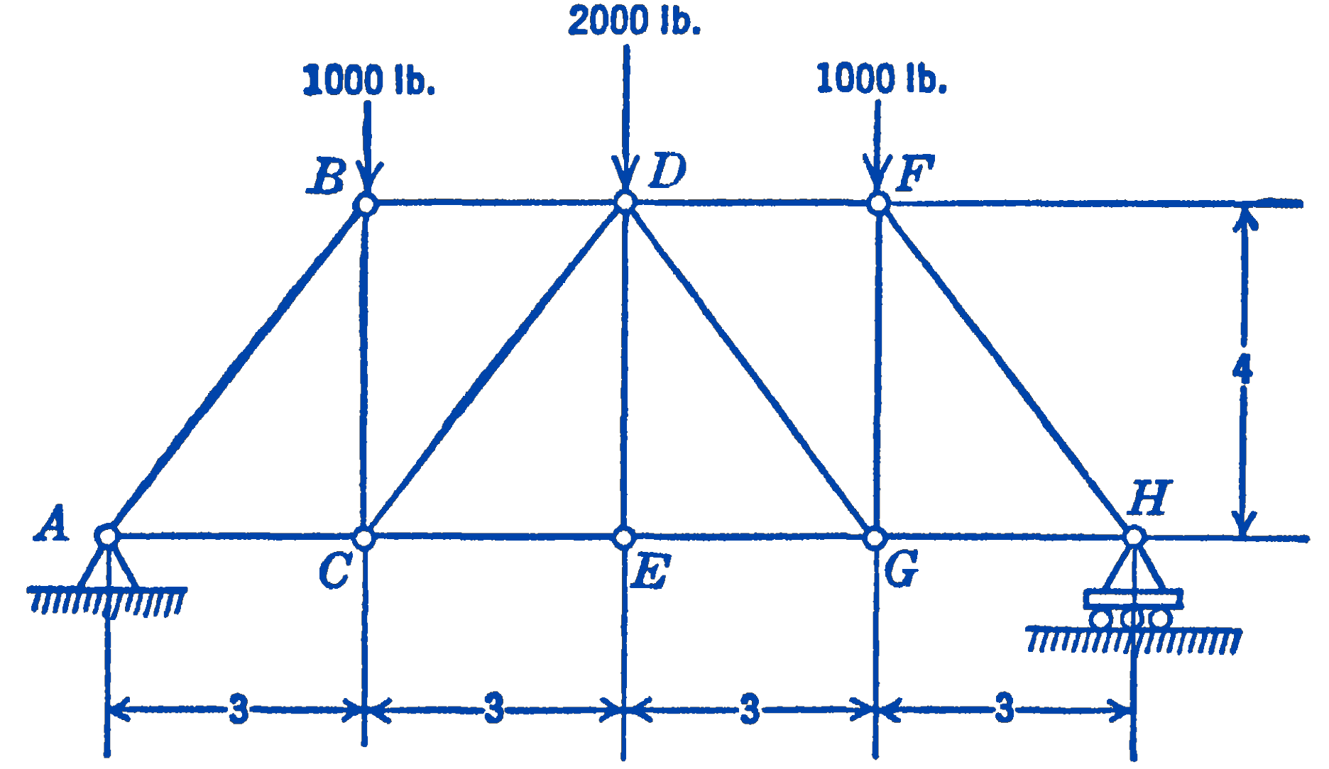
1. Find the forces in the members of the truss shown in the diagram by the method of joints. Check the force in the member \(C E\) by the method of sections.
Answer
\(B D=1500 \ \mathrm{lb}\ (\mathrm{C})\), \(C D=1250\ \mathrm{lb}\ (\mathrm{C})\)
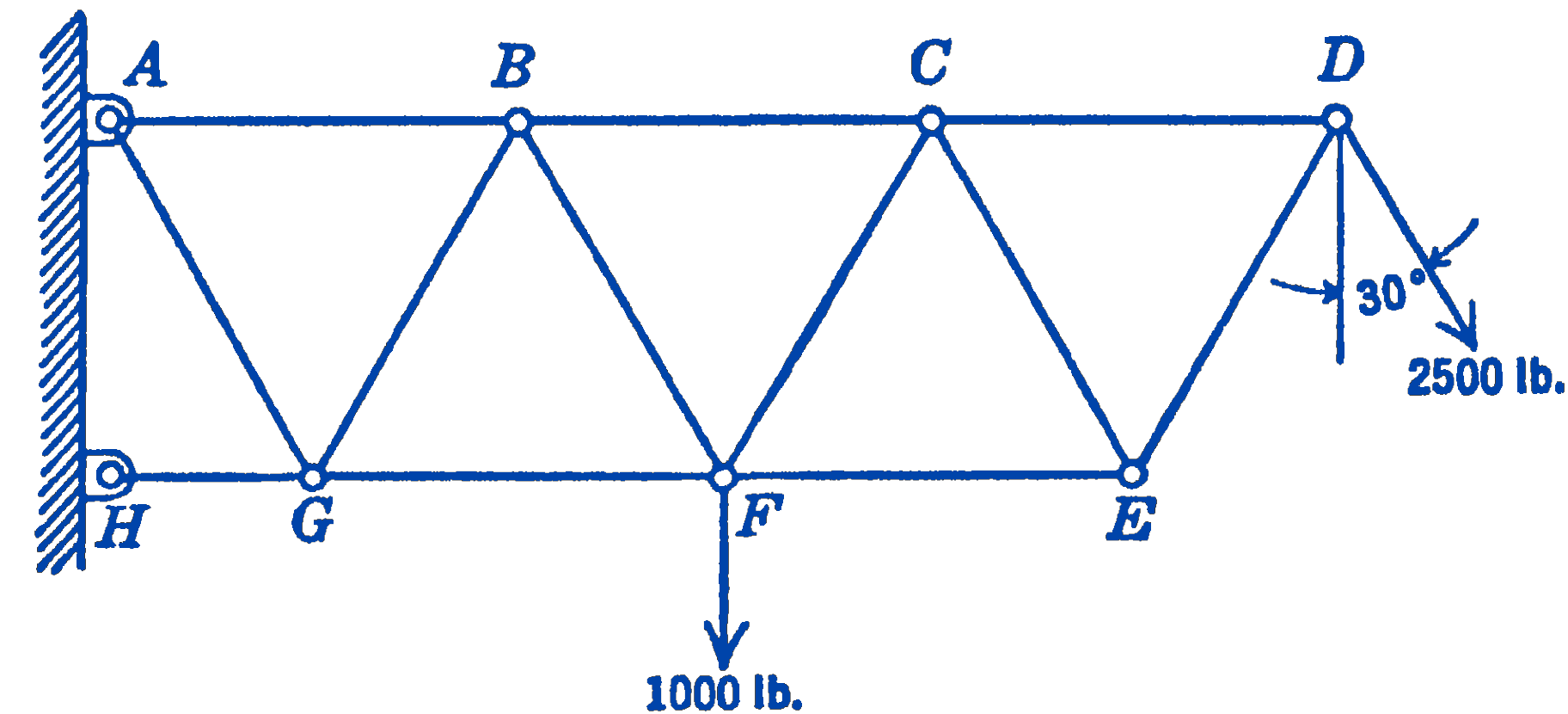
2. All of the members of the truss shown in the diagram have the same length \(l\) except \(G H\), which has a length \(\frac{l}{2}\). Find the force in each member by the method of joints, and check the force in the member \(F G\) by the method of sections.
Answer
\(A B=8660 \ \mathrm{lb}\ (\mathrm{T})\), \(F G=5580 \ \mathrm{lb}\ (\mathrm{C})\)
3.
- Show that if two non-colinear members only meet at a joint, and there is no external load on the joint, the forces in both members must be zero.
- Show that if three members meet at a joint with no external load, and two of the members are colinear, the force in the third member is zero.
4. Find the force in the central vertical member marked \(l\) in the truss shown in the figure.

Answer
\(F\)
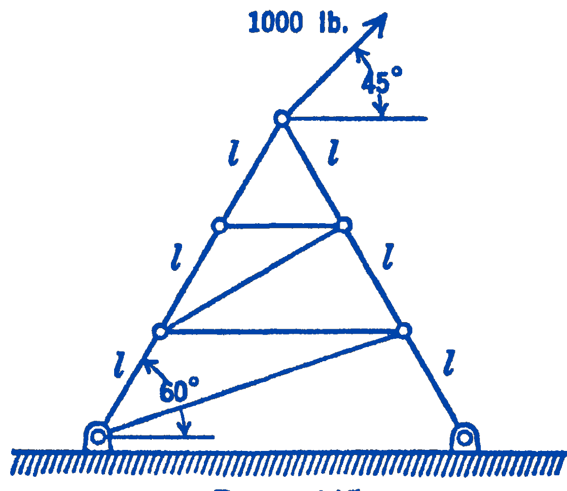
5. Find the forces in the members of the truss shown in the diagram.
Answer
\(1115 \ \mathrm{lb}\ (\mathrm{T}), 298 \ \mathrm{lb}\) (C)
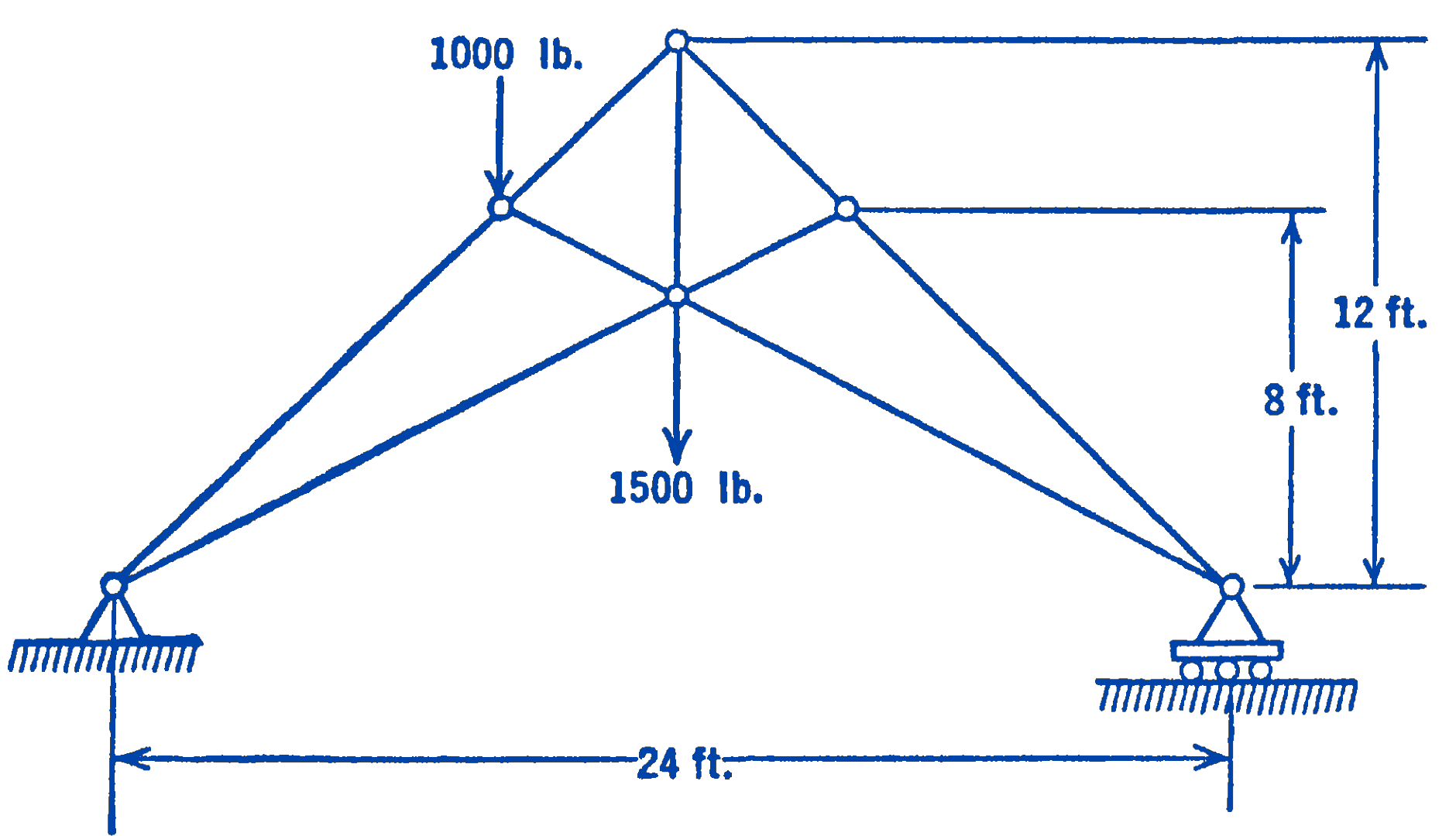
6. Find the force in each member of the truss shown in the figure.
Answer
Center vertical member \(F=4330 \ \mathrm{lb}\) (T)