If the general force system is to be in equilibrium, both the resultant force and the resultant couple must be equal to zero, and the conditions for equilibrium become: \[ \begin{aligned} & \mathbf{R}=\sum \mathbf{F}=\mathbf{0} \\ & \mathbf{C}=\sum \mathbf{M}=\mathbf{0} \end{aligned} \]
It is convenient usually to describe the force system in a rectangular coordinate system. Since the force and the couple vector can be zero only if their three rectangular coordinates are zero, the general equations of equilibrium become: \[ \left\{\begin{array}{r} \sum F_{x}=0 \\ \sum F_{y}=0 \\ \sum F_{z}=0 \\ \sum M_{x}=0 \\ \sum M_{y}=0 \\ \sum M_{z}=0 \end{array}\right. \]
Since it requires three quantities to specify the force vector in any coordinate system, and an additional three to specify the couple vector, there are six independent equations available to express the conditions of equilibrium. For a system of forces in equilibrium, the sum of the forces along any arbitrary axis is zero, and the sum of the moments about any arbitrary axis is zero, so that any number of valid equations can be written. All these equations, however, will not be independent. For any particular force system, the number of independent equations of equilibrium which can be written is equal to the number of quantities which must be given in order to specify completely the resultant of the force system. A knowledge of the number of independent equations which can be written for any particular system is of importance because this specifies the maximum number of unknown quantities which can be determined by the equations of equilibrium.
The number of such independent equations available for the various force systems are:
- The General Three-dimensional Force System. Six independent equations may be written. These may be all moment equations, or as many as three of the equations may be force equations.
- The General Concurrent System. The resultant of this system is a single force which requires three components for its complete specification. There are thus three independent equations of equilibrium. These equations may be force equations, moment equations, or both force and moment equations.
- The General Coplanar System. Three quantities will specify completely the resultant of a general system of forces in one plane, so three equilibrium equations are available. Either force or moment equations can be used, except that a maximum of two force equations can be written.
- The General Parallel System. In a system of parallel forces in space three equations can be written. These will ordinarily be one force equation and two moment equations.
- Coplanar Parallel System. Two equations, either a force and a moment equation, or two moment equations may be written.
- Concurrent Coplanar System. Two equations, either forces, moments, or moments and forces, may be written.
- Colinear Systems. One equation, either a force or a moment equation, may be used.
In practice, one selects the type of equation and the axes along which forces are to be summed or about which moments are to be summed, according to the particular conditions of the problem. For most problems the use of certain axes will result in simpler equations than the use of other possible axes, so that one should examine each problem carefully and select the most appropriate set of equations. Moment equations, for example, can often be simplified by selecting a moment axis which intersects the lines of action of several of the forces of the system. In this way equations involving only one or two unknowns can often be obtained.
Example. A crane consisting of a vertical rigid bar \(A D\) which is pivoted at \(D\) is supported by two guy wires \(A E\) and \(A F\) (Fig. 1).
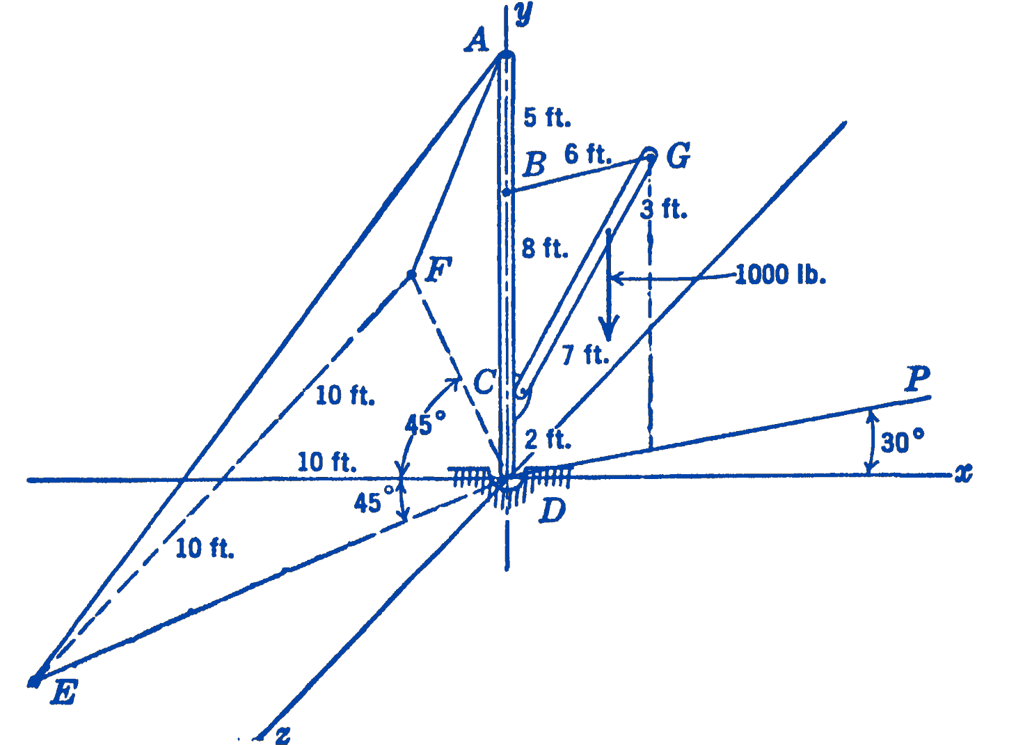
A vertical load of \(1000\ \mathrm{lb}\) is picked up by the boom \(C G\) which is supported by the guy wire \(B G\), the whole configuration of the system being shown in the diagram. Find all of the forces exerted on the bar \(A D\). The weights of the bars are small compared with the other forces acting and hence in this problem may be neglected
Solution. We first draw a free-body diagram (Fig. 2) of the bar \(A D\).
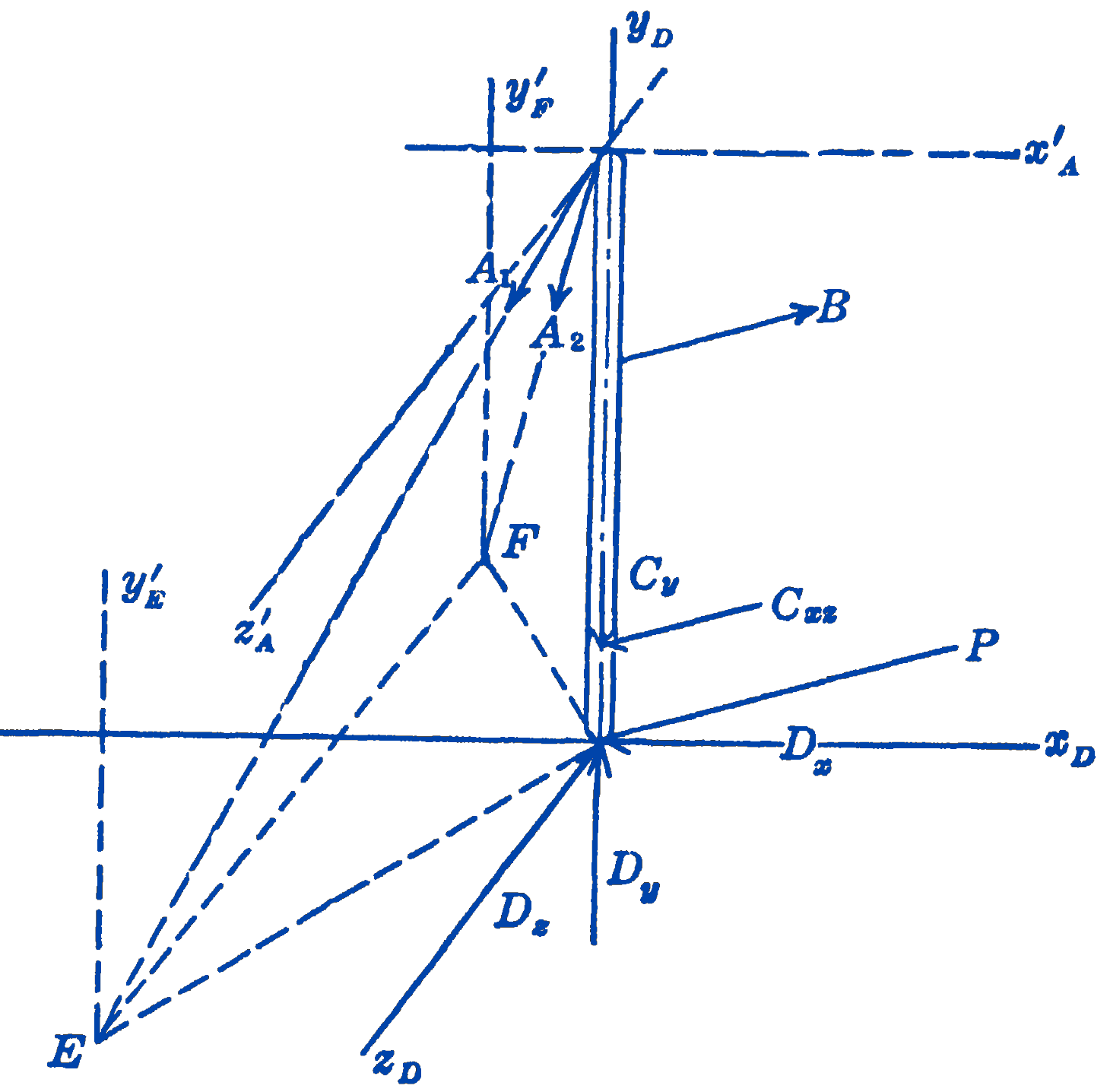
The forces in the guy wires at \(A\) and \(B\) are known to be in the direction of the guy wires, and hence may be drawn in their proper direction on the free-body diagram. The force at \(C\) must lie in the plane of the boom \(C G\) and the guy wire \(B G\), but since we do not know the direction in this plane, we indicate the force by two unknown components \(C_{y}\) and \(C_{x z}\) where \(C_{x z}\) is parallel to the \(x z\) plane. The force at \(D\) is completely unknown and may be in any position in space, so that we indicate this force by three rectangular components \(D_{x}, D_{y}\), and \(D_{z}\). We now note that we have eight unknown quantities in the problem, whereas we can write down only six independent equations for the general force system. It is thus apparent that we cannot determine all of the forces from the free-body diagram shown in the diagram, and we examine the possibility of determining some of the forces from a free-body diagram of some other portion of the structure. We next draw the free-body diagram (Fig. 3) of the boom \(C G\).
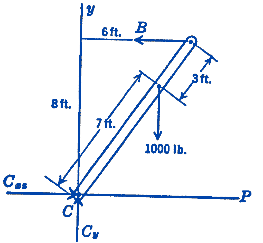
For this general coplanar system three equations can be written and hence the forces \(C_{y}, C_{x z}\), and \(B\) can be determined. Having thus found three of the eight unknown elements of the original free-body diagram, the six equations which can be written for that free-body diagram will suffice to complete the solution of the problem.
For the free-body diagram of the boom \(B C\), we have: \[ \begin{aligned} &\sum F_{P} =0=C_{x z}-B \\ &\sum F_{y} =0=C_{y}-1000 ; \quad C_{y}=1000 \mathrm{lb} \\ &\sum M_{C} =0=(8)(B)-\left(\frac{3}{5}\right)(7)(1000) ; \quad B=525\ \mathrm{lb} \text { (tension) } \end{aligned} \] and from the first equation \[ C_{x z}=525\ \mathrm{lb}. \]
Since all of the forces came out with positive signs, we know that we chose the correct directions for the unknown components. Note that the forces \(B\), \(C_{y}\) and \(C_{x z}\) in the second free-body diagram are equal and opposite to the forces \(B, C_{y}\), and \(C_{x z}\) in the first free-body diagram.
Returning now to the first free-body diagram and writing the equations in each case for the axis which will yield the simplest result, we have: \[ \begin{aligned} \sum M_{E F}=0=&-10 B_{x}+2 C_{xz}-10 C_{y}+10 D_{y} \\ =&(10)(525)(0.866)+(2)(525)(0.866)-(10)(1000) \\ & +10 D_{y} \end{aligned} \] Therefore, \[ D_{y}=1364\ \mathrm{lb} \] Therefore, \[ D_{x}=-242\ \mathrm{lb} \]
Since \(D_{x}\) comes out with a negative sign, we know that the direction was incorrectly shown on the free-body diagram, and that the force is actually opposite to the force shown there. \[ \begin{aligned} \sum M_{x^{\prime}_A}=0&= 5 B_{z}-13 C_{z}+15 D_{z} \\ &=(5)(525)(0.500)-(13)(525)(0.500)+15 D_{z} \end{aligned} \]
Therefore,
\[D_{z}=140 \mathrm{lb}\] \[ \begin{aligned} \sum M_{y'_E}=0=&\frac{10}{\sqrt{(10)^{2}+(10)^{2}+(15)^{2}}}\left(A_{2}\right)(20)+10 D_{z}+10 D_{z} \\ =&\frac{20}{20.6}\left(A_{2}\right)-242+140 \end{aligned} \] Therefore, \[ A_{2}=105\ \mathrm{lb} \] \[ \begin{aligned} \sum M_{y'_F}=0=&-\frac{10}{\sqrt{(10)^{2}+(10)^{2}+(15)^{2}}}\left(A_{1}\right)(20)+10 D_{z}+10 D_{z} \\ =&-\frac{20}{20.6} A_{1}+242+140 \end{aligned} \] Therefore, \[ A_{1}=394\ \mathrm{lb} \]
As a check equation, we may write:
\[ \begin{aligned} \sum F_{y}=0 & =-\left(\frac{15}{20.6}\right)(394)-\left(\frac{15}{20.6}\right)(105)-1000+1364 \\ & =-287-77-1000+1364=0 \end{aligned} \]
2.1.1 PROBLEMS
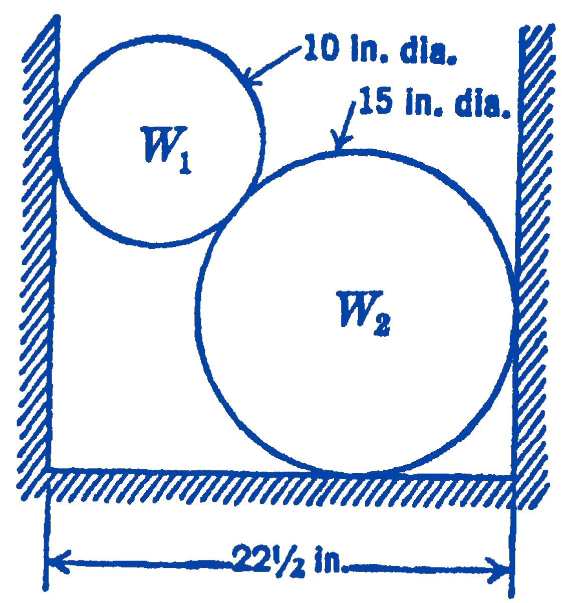
1. Two homogeneous circular cylinders are supported in a trough as shown in the figure. The weight of \(W_{1}\) is \(250\ \mathrm{lb}\), and the weight of \(W_{2}\) is \(750\ \mathrm{lb}\). Find the forces exerted by \(W_{1}\) on \(W_{2}\), and by the two cylinders on the walls and floor of the trough.
2. Three loads act on a simply supported beam as shown in the diagram. Find the forces exerted on the beam by the two supports. Solve for these forces from two moment equations, and check by means of a force equation. The weight of the beam is assumed to be small compared to the loads acting and is neglected. Write a third moment equation about some point not used for the first two moment equations, and show that this third equation is not independent, but can be formed from the first two equations.
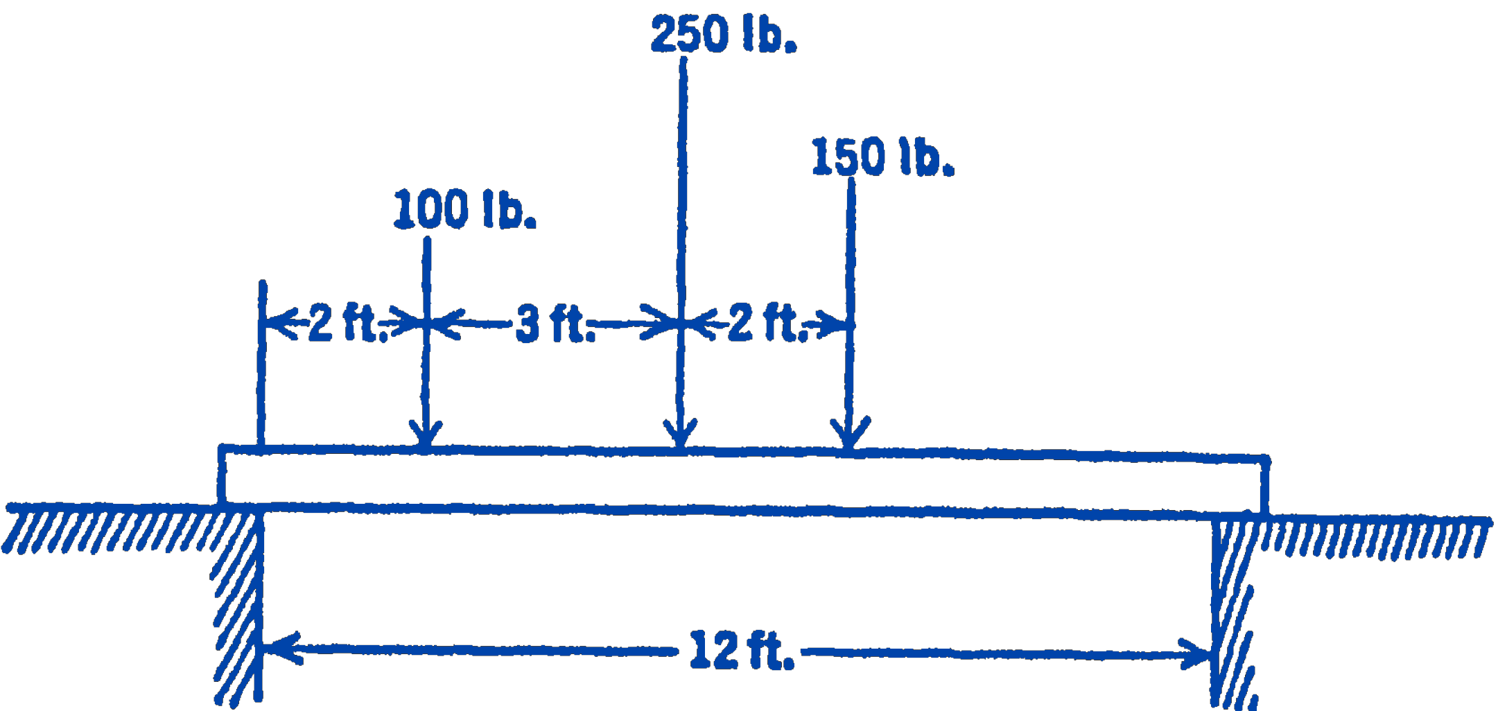
Answer
\(292 \mathrm{lb} ; 208 \mathrm{lb}\)
3. A \(100\ \mathrm{lb}\) weight is suspended from the end of a \(3\ \mathrm{ft}\) long weightless rod as is shown in the diagram. Find the angle \(\theta\) for equilibrium of the system. Assume that the surfaces in contact are frictionless, i.e., the force at \(B\) is normal to the \(\operatorname{rod} A C\).
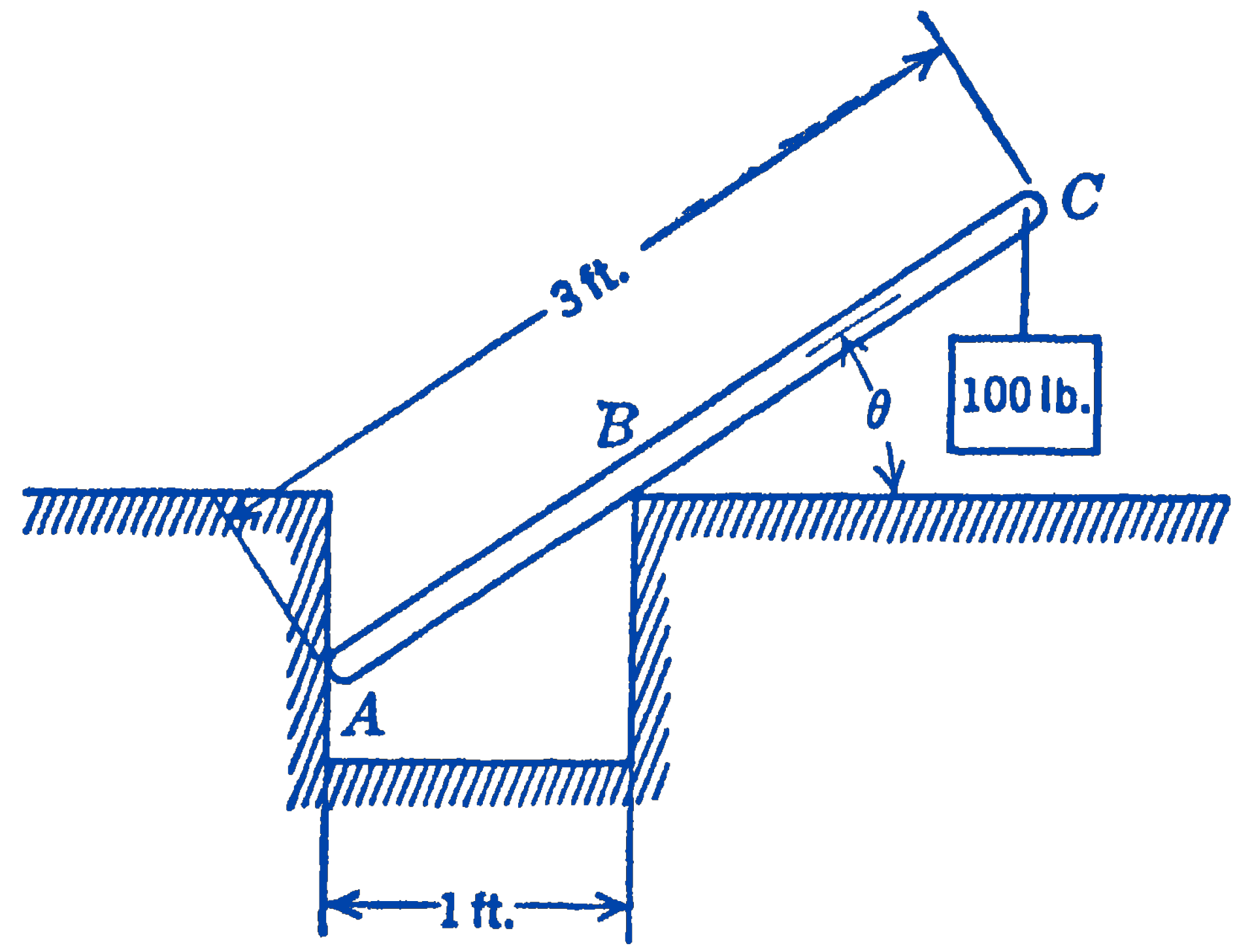
Answer
\(46^{\circ} 8^{\prime}\)
4. Show that for a general coplanar system three moment equations are sufficient to insure equilibrium only in the case that the three moment centers are not colinear.
5. Show that three concurrent forces which are not coplanar cannot be in equilibrium.
6. A roller has a radius of \(18\ \mathrm{in}\) and a weight of \(500\ \mathrm{lb}\). What force must be applied as shown in the diagram to just lift the roller over a \(2\ \mathrm{in}\) obstacle; i.e., to reduce the vertical reaction on the roller to zero?
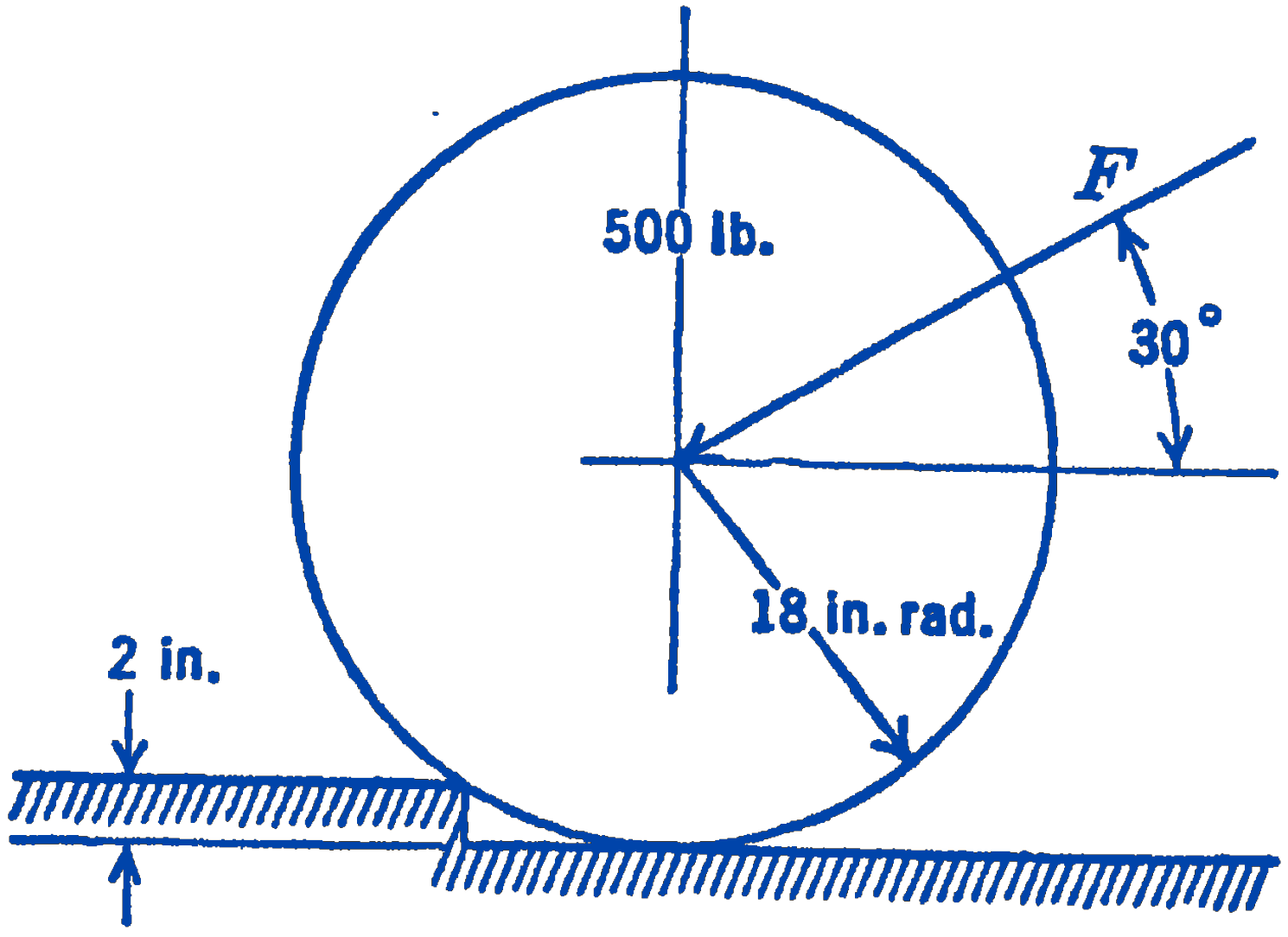
Answer
424 lb
7. The pole \(A C\), lying in the \(x y\) plane, is supported by two horizontal cables \(B D\) and \(B E\) as shown in the figure. A 1000 lb horizontal force acts at the end of the pole and makes an angle of \(30^{\circ}\) with the \(x y\) plane as shown. Find the force at \(A\), and the forces in the cables.
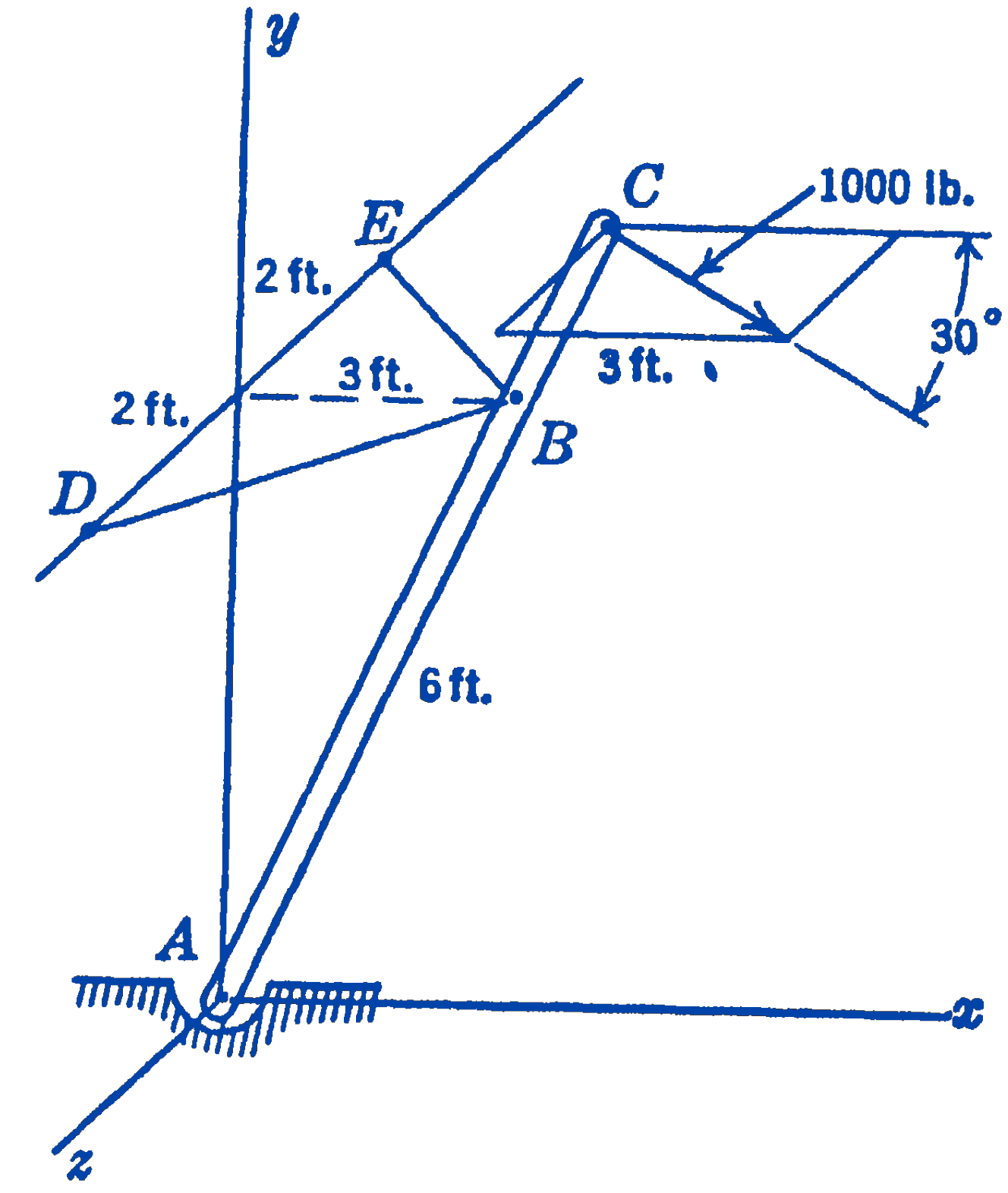
Answer
\(D=105\ \mathrm{lb}\ (\mathrm{T}) ; E=1455\ \mathrm{lb}\(\mathrm{T})\); \(A=500\ \mathrm{lb}\)
8. Show that if three coplanar, non-parallel forces are in equilibrium, they must be concurrent.