A general analytical method can now be developed for determining the resultant of any three-dimensional force system. The method consists of replacing each force of the system by an equivalent force passing through a particular point and a couple. These forces and couples may then easily be added to give the resultant force and the resultant couple for the whole system. The method is indicated in Fig. 1 where, for simplicity, two forces only are shown. The method is valid, however, for any number of forces.
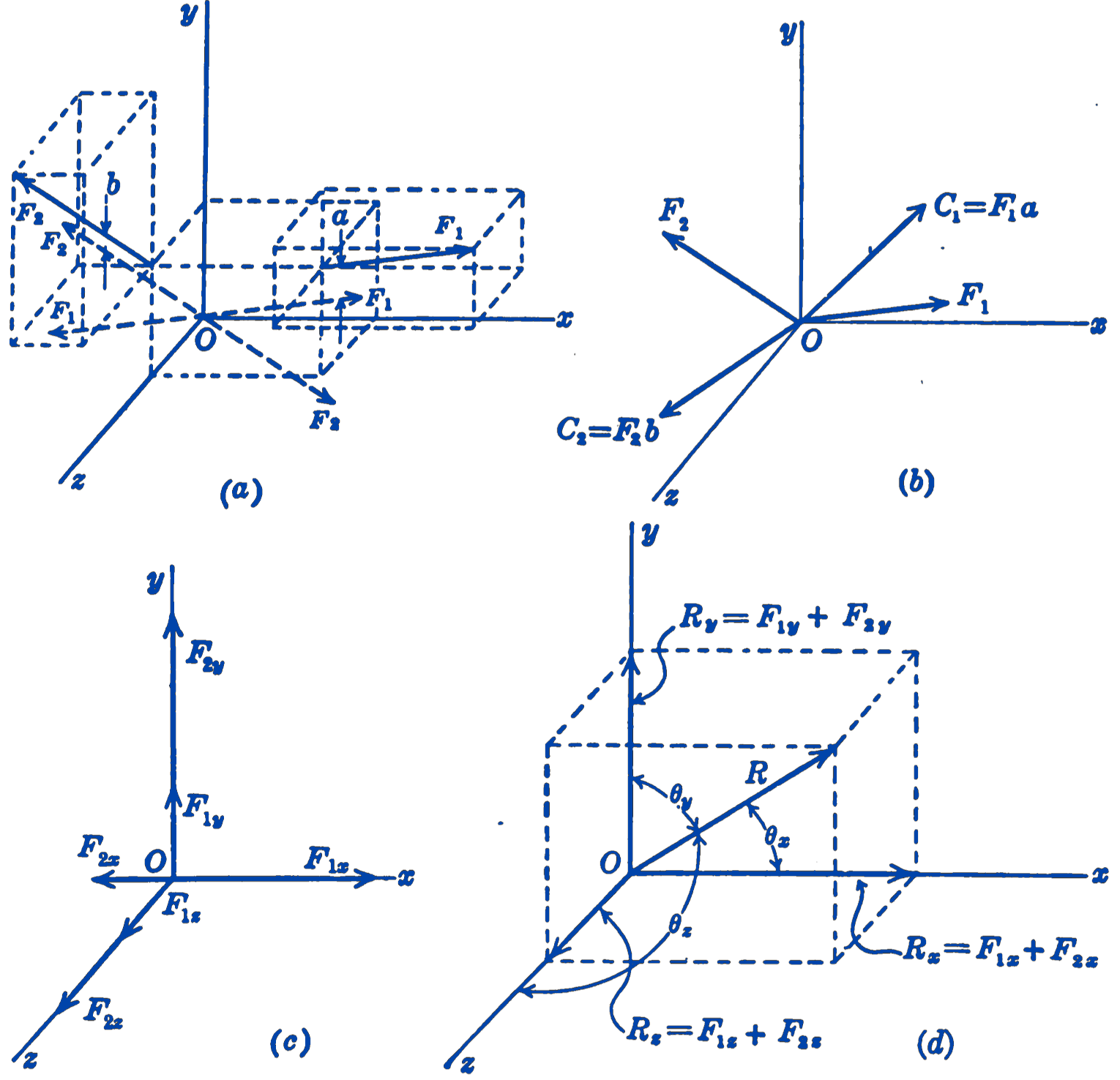
In Fig. 1a the two general forces \(\mathbf{F}_1\) and \(\mathbf{F}_2\) are given and the problem is to determine their resultant. We resolve each force into a parallel force, through the origin of a rectangular coordinate system, and a couple \(\mathbf{C}\), thus reducing the system to a set of concurrent forces and couples as shown in (b). Each of the concurrent forces can be resolved into components along the three coordinate axes as in (c), and the sum of these rectangular components will give the rectangular components of the resultant force \(\mathbf{R}\) which can then be found as in (d). The couple vectors can be added in exactly the same way, and hence the general force system is reduced to a force and a couple given by: \[ R = \sqrt{R_x^2 + R_y^2 + R_z^2}; \]\[ \theta_x = \cos^{-1} \frac{R_x}{R},\quad \theta_y = \cos^{-1} \frac{R_y}{R},\quad \theta_z = \cos^{-1} \frac{R_z}{R} \] where \[ R_x = \sum F_x; \quad R_y = \sum F_y; \quad R_z = \sum F_z \] and \[ C = \sqrt{C_x^2 + C_y^2 + C_z^2}; \] \[ \phi_x = \cos^{-1} \frac{C_x}{C},\quad \phi_y = \cos^{-1} \frac{C_y}{C},\quad \phi_z = \cos^{-1} \frac{C_z}{C} \] where \[ C_x = \sum M_x; \quad C_y = \sum M_y; \quad C_z = \sum M_z \]
In practice, it is not necessary to imagine that the forces have been resolved into forces and couples, as in Fig. 1. Since the forces at the origin will always be parallel to the corresponding forces in their original position, the rectangular components of the forces in their original system will be the same as the rectangular coordinates of the concurrent force system. In the case of the couples, one of the forces of each couple passes through the origin and hence has a zero moment about the three coordinate axes. The moment of each of the original forces about one of the coordinate axes will thus equal the component of the couple vector along that axis. We need only consider the general force system in its given position, and write: \[ R_x = \sum F_x; \quad R_y = \sum F_y; \quad R_z = \sum F_z; \] \[ R = \sqrt{R_x^2 + R_y^2 + R_z^2}; \] \[ \theta_x = \cos^{-1} \frac{R_x}{R},\quad \theta_y = \cos^{-1} \frac{R_y}{R},\quad \theta_z = \cos^{-1} \frac{R_z}{R} \] \[ C_x = \sum M_x; \quad C_y = \sum M_y; \quad C_z = \sum M_z;\] \[C = \sqrt{C_x^2 + C_y^2 + C_z^2};\]\[\phi_x = \cos^{-1} \frac{C_x}{C}, \phi_y = \cos^{-1} \frac{C_y}{C}, \phi_z = \cos^{-1} \frac{C_z}{C} \]
This method reduces any general three-dimensional force system to a single force and a single couple. For most problems this is as far as it is necessary to reduce such force systems. In fact, in most engineering problems, the components of the force and the couple along the coordinate axes are wanted, so that usually it will not be necessary to calculate the resultant force and moment. A system of a force and a couple can always be resolved into a force passing through a particular point and a couple whose vector is parallel to the force, i.e., the couple vector can be made parallel to the force vector. The axis along which the force vector acts is in this case called the central axis of the system.
The analysis of force systems along the lines outlined above was first made by Louis Poisson (1777-1859) and treated in his two principal works, the Éléments de Statique (1803) and the Nouvelle Théorie de la Rotation des Corps (1834). In these works, along with other important contributions to dynamics, he developed the theory of couples and of the central axis and, for the first time, systematized the solution of general force systems.
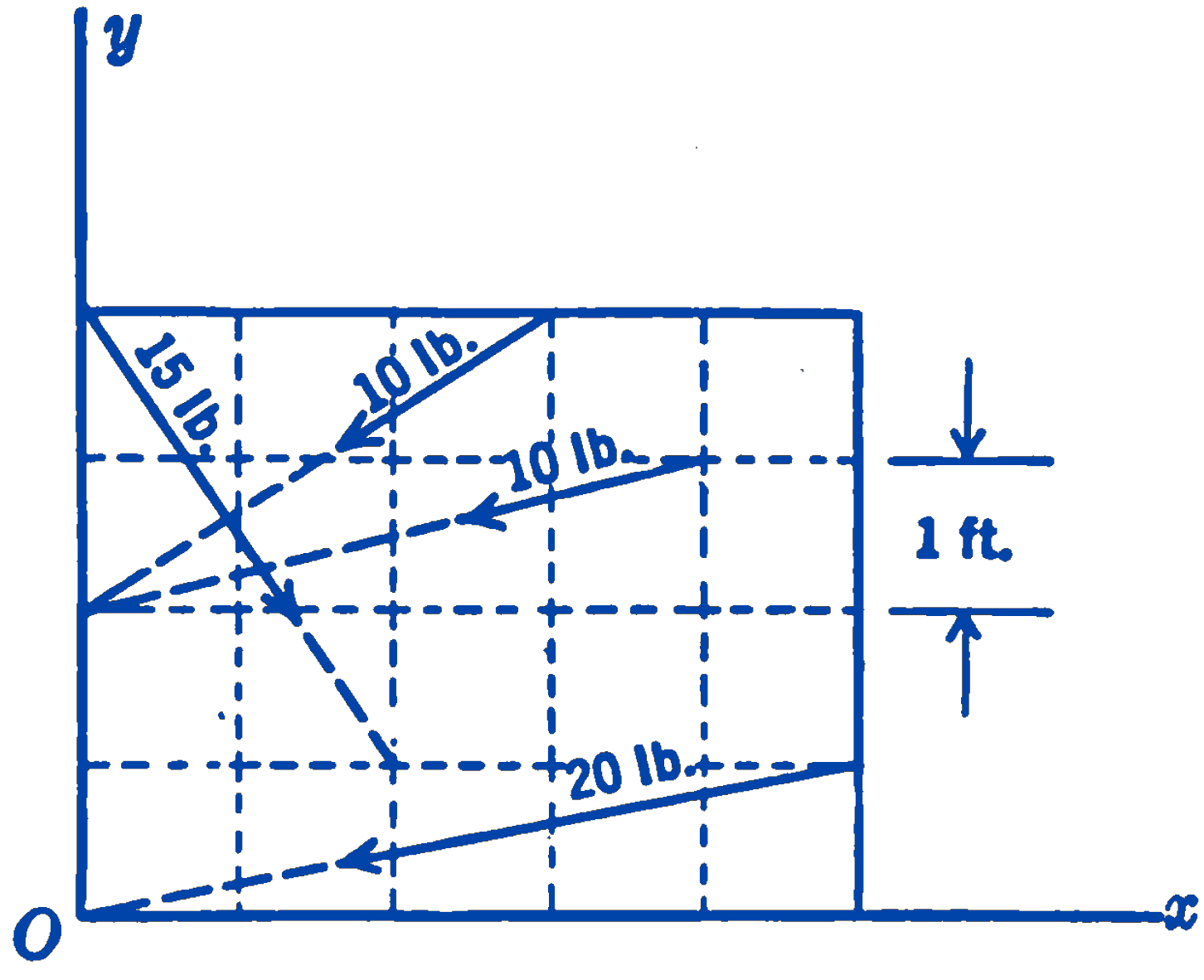
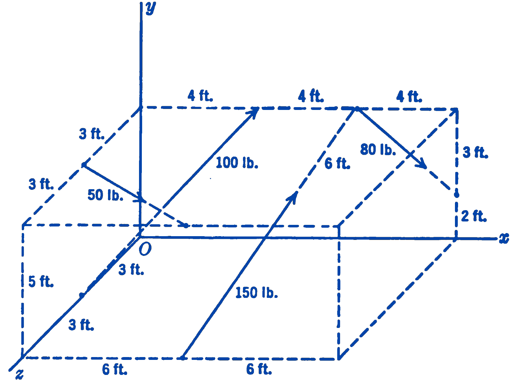
Example 1 Find the resultant of the force system shown in Fig. 2.
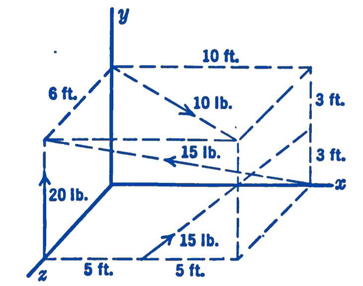
Solution: \[ \begin{aligned} R_x =& \sum F_x \\ =& + (10) \frac{10}{\sqrt{(6)^2 + (10)^2}} - (15) \frac{10}{\sqrt{(6)^2 + (6)^2 + (10)^2}} \\ &+ (15) \frac{5}{\sqrt{(3)^2 + (5)^2 + (6)^2}} \\ =& + 8.58 - 11.45 + 8.96 = 6.09 \, \text{lb} \end{aligned} \]
\[ \begin{aligned} R_y =& \sum F_y \\ =& + 20 + (15) \frac{6}{\sqrt{(6)^2 + (6)^2 + (10)^2}} \\ &+ (15) \frac{3}{\sqrt{(3)^2 + (5)^2 + (6)^2}} \\ =& + 20.0 + 6.87 + 5.38 = 32.25 \, \text{lb} \end{aligned} \]
\[ \begin{aligned} R_z =& \sum F_z \\ =& + (10) \frac{6}{\sqrt{(6)^2 + (10)^2}} + (15) \frac{6}{\sqrt{(6)^2 + (6)^2 + (10)^2}} \\ &- (15) \frac{6}{\sqrt{(3)^2 + (5)^2}} \\ =& + 5.15 + 6.87 - 10.76 \\ =& 1.26 \, \text{lb} \end{aligned} \]
Thus the resultant force is the vector: \[ \mathbf{R} = 6.09 \mathbf{i} + 32.25 \mathbf{j} + 1.26 \mathbf{k} \, \text{lb} \]
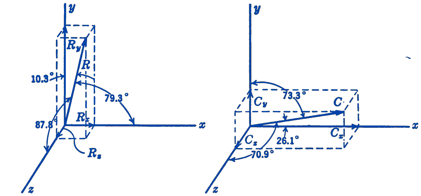
The magnitude and direction of this vector can be found if desired: \[ R = \sqrt{(6.09)^2 + (32.25)^2 + (1.26)^2} = 32.8 \, \text{lb} \] \[ \theta_x = \cos^{-1} \frac{6.09}{32.8} = \cos^{-1} 0.1852 = 79.3^\circ \] \[ \theta_y = \cos^{-1} \frac{32.25}{32.8} = \cos^{-1} 0.9840 = 10.3^\circ \] \[ \theta_z = \cos^{-1} \frac{1.26}{32.8} = \cos^{-1} 0.0384 = 87.8^\circ \]
\[ \begin{aligned} C_x = \sum M_x =& - (20)(6) + \frac{(10)(6)(6)}{\sqrt{(6)^2 + (10)^2}} \\ &- \frac{(15)(6)(3)}{\sqrt{(3)^2 + (5)^2}} \\ =& - 120 + 31.2 - 32.3 \\ =& 121.1 \, \text{ft-lb} \end{aligned} \]
\[ \begin{aligned} C_y = \sum M_y =& \frac{(15)(6)(10)}{\sqrt{(6)^2 + (6)^2 + (10)^2}} + \frac{(15)(6)(10)}{\sqrt{(3)^2 + (5)^2 + (6)^2}} \\ &- \frac{(10)(6)(6)}{\sqrt{(6)^2 + (6)^2 + (10)^2}} \\ =& - 68.7 + 107.6 - 32.3 \\ =& 38.9 \, \text{ft-lb} \end{aligned} \]
\[ \begin{aligned} C_z = \sum M_z =& \frac{(15)(6)(5)}{\sqrt{(6)^2 + (6)^2 + (10)^2}} + \frac{(15)(10)(6)}{\sqrt{(3)^2 + (5)^2}} \\ &- \frac{(15)(6)(10)}{\sqrt{(6)^2 + (6)^2 + (10)^2}} \\ =& + 68.7 + 26.9 - 51.5 \\ =& 44.1 \, \text{ft-lb} \end{aligned} \]
\[ \mathbf{C} = 121.1 \mathbf{i} + 38.9 \mathbf{j} + 44.1 \mathbf{k} \, \text{ft-lb} \]
\[ C = \sqrt{(121.1)^2 + (38.9)^2 + (44.1)^2} = 135 \, \text{ft-lb} \]
\[ \phi_x = \cos^{-1} \frac{121.1}{135} = \cos^{-1} 0.898 = 26.1^\circ \] \[ \phi_y = \cos^{-1} \frac{38.9}{135} = \cos^{-1} 0.288 = 73.3^\circ \] \[ \phi_z = \cos^{-1} \frac{44.1}{135} = \cos^{-1} 0.327 = 70.9^\circ \]
The resultant force and couple are shown in Fig. 3.
Example 2. Find the resultant of the system of parallel forces shown in Fig. 4.
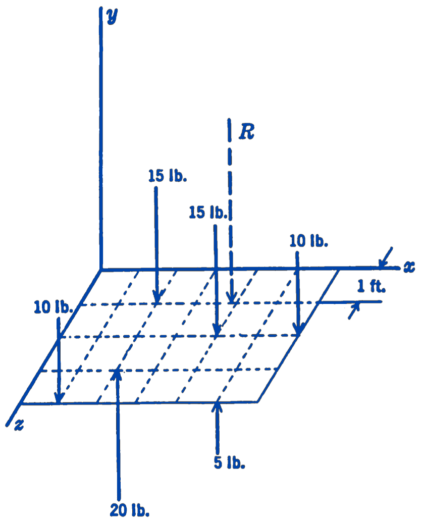
Solution. We note that for any parallel force system the forces of the resultant couple can be arranged parallel to the resultant force, and hence that the resultant couple and the resultant force can always be resolved into a single force or a single couple. Instead of applying the general method to this problem, therefore, we shall use the principle of moments directly to find the location of the resultant force: \[ R = \sum F = -10 - 15 - 10 + 5 + 20 = -25 \text{ lb} \] The distance \(z\) of the resultant from the \(xy\) plane can be found by taking moments about the \(x\)-axis: \[ \begin{aligned} R(z) = \sum M_x =& (1)(15) + (2)(15) + (2)(10) + (4)(10) \\ &- (3)(20) - (4)(5) \\ =& 15 + 30 + 20 + 40 - 60 - 20 \\ =& +25 \text{ ft}\cdot\text{lb} \end{aligned} \] The downward resultant must be in such a position as to give a positive moment about the \(x\)-axis. \[ z = \frac{\sum M_x}{R} = \frac{25 \text{ ft-lb}}{25 \text{ lb}} = 1 \text{ ft\ in front of the $xy$ plane.} \] The distance \(x\) of the resultant from the \(yz\) plane can be found by taking moments about the \(z\)-axis: \[ \begin{aligned} R(x) = \sum M_z =& -1(10) + (2)(20) - (2)(15) - (4)(15) \\ &+ (5)(5) - (6)(10) \\ =& -10 + 40 - 30 - 60 + 25 - 60 \\ =& -95 \text{ ft}\cdot\text{lb} \end{aligned} \] The downward resultant must be in such a position as to give a negative moment about the \(z\)-axis. \[ x = \frac{\sum M_z}{R} = \frac{-95 \text{ ft-lb}}{-25 \text{ lb}} = 3.8 \text{ ft \ to the right of the $yz$ plane.} \] It should be observed that in general it is not possible to define the sign of a moment by taking the product of the sign of the moment arm and the sign of the force.
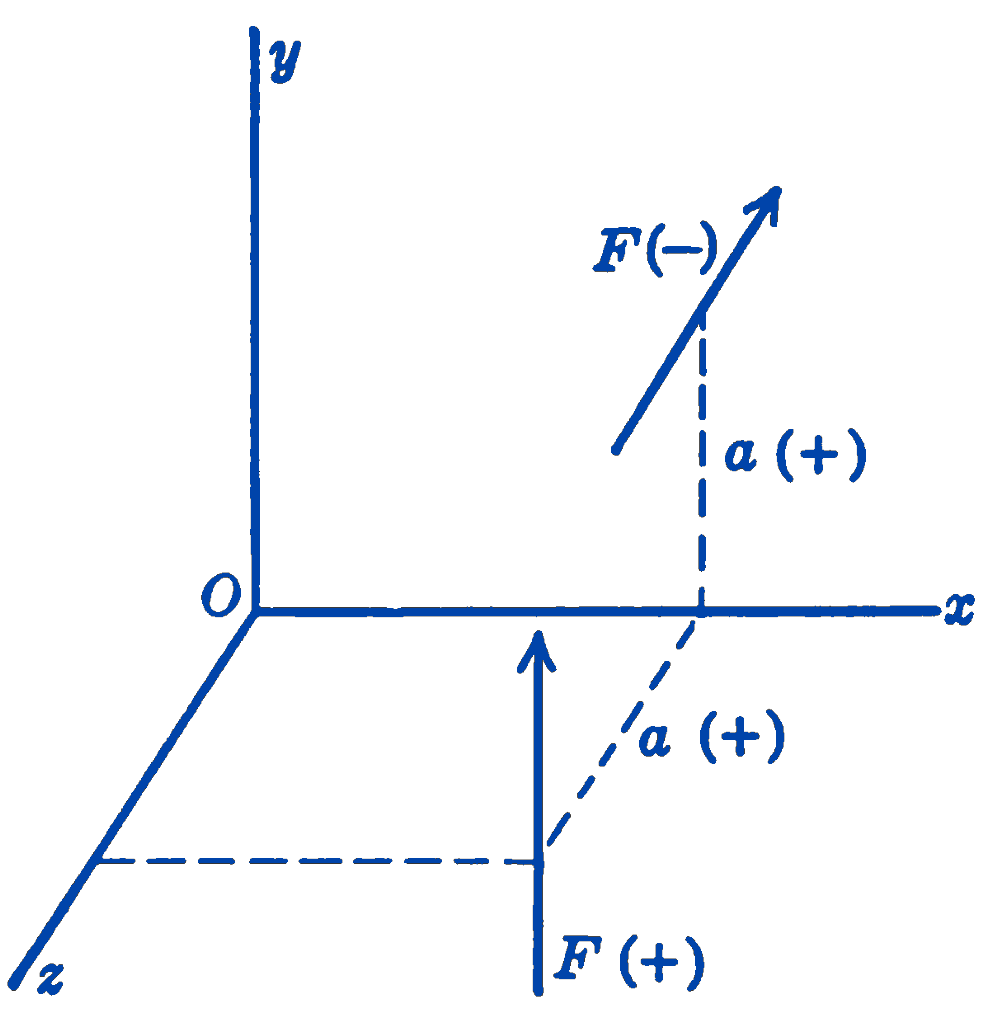
In Fig. 5 are seen two forces \(\mathbf{F}\) which have the same direction of moment about the \(x\)-axis. In each case the direction of the moment is counterclockwise as one looks from the origin towards the positive end of the \(x\)-axis; hence by the right-hand screw rule the moments are negative. For the force parallel to the \(y\)-axis, the force is positive and the moment arm is positive, so that the product is positive. For the force parallel to the \(z\)-axis, the force is negative and the moment arm is positive, hence the product is negative. It will thus be apparent that no sign convention will give entire consistency between directions of forces, arms, and moments. The use of vector notation eliminates any difficulty of this kind.
1.13.1 PROBLEMS
1. Three forces act on a beam as shown in the diagram. (a) Find the resultant of the system. (b) Resolve this resultant into two components at the points \(A\) and \(B\).
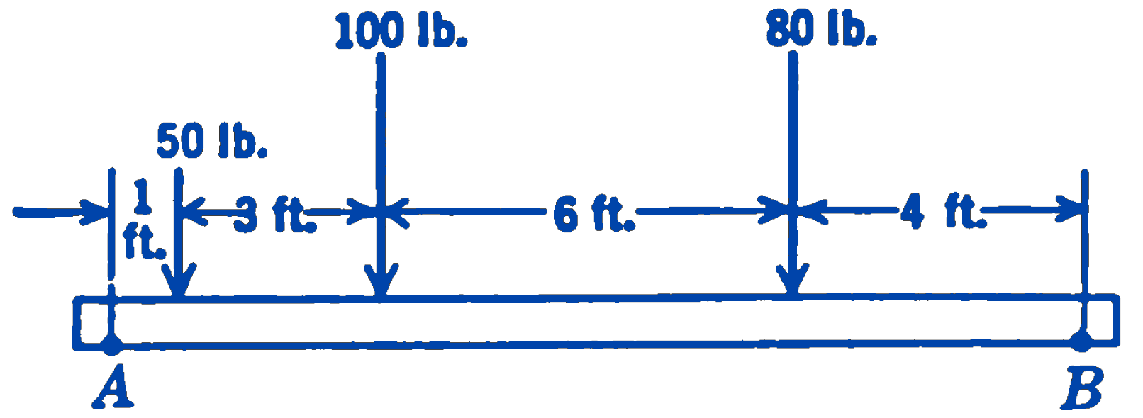
Answer
230 lb; \(F_A = 141\) lb, \(F_B = 89\) lb
2. Five forces which are parallel to the y-axis intersect the \(xz\) plane at the following points:
\[ \begin{aligned} &F_1 = 100\, \text{lb},\ x = 2,\ z = 3; \\ &F_2 = 150\, \text{lb},\ x = 1,\ z = -1; \\ &F_3 = 80\, \text{lb},\ x = -3,\ z = 5; \\ &F_4 = -50\, \text{lb},\ x = 3,\ z = 3; \\ &F_5 = -100\, \text{lb},\ x = 5,\ z = 2 \end{aligned} \] Find the resultant of the system.
Answer
180 lb; \(x = -3.0\), \(z = 1.11\)
3. A force of 50 lb acts vertically downward, parallel to the y-axis, and intersects the \(xz\) plane at the point \(x = 2\), \(z = 3\). Resolve this force into three parallel components acting at the points \(x = 0\), \(z = 0\); \(x = 5\), \(z = 0\); \(x = 0\), \(z = 4\).
Answer
-7.5 lb, 20 lb, 37.5 lb
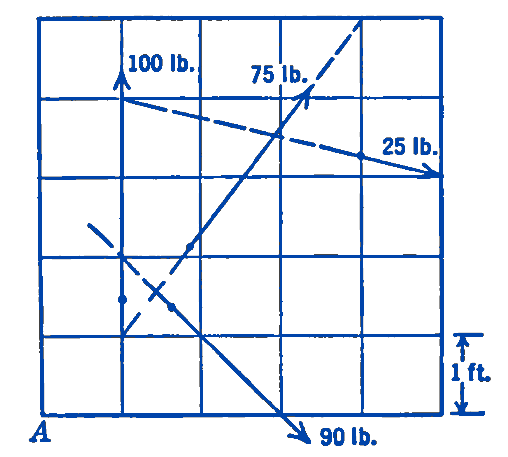
4. Find the resultant of the force system shown in the diagram.
Answer
Magnitude of force = 38.2 lb
5. Find the resultant of the three concurrent forces shown in the figure.
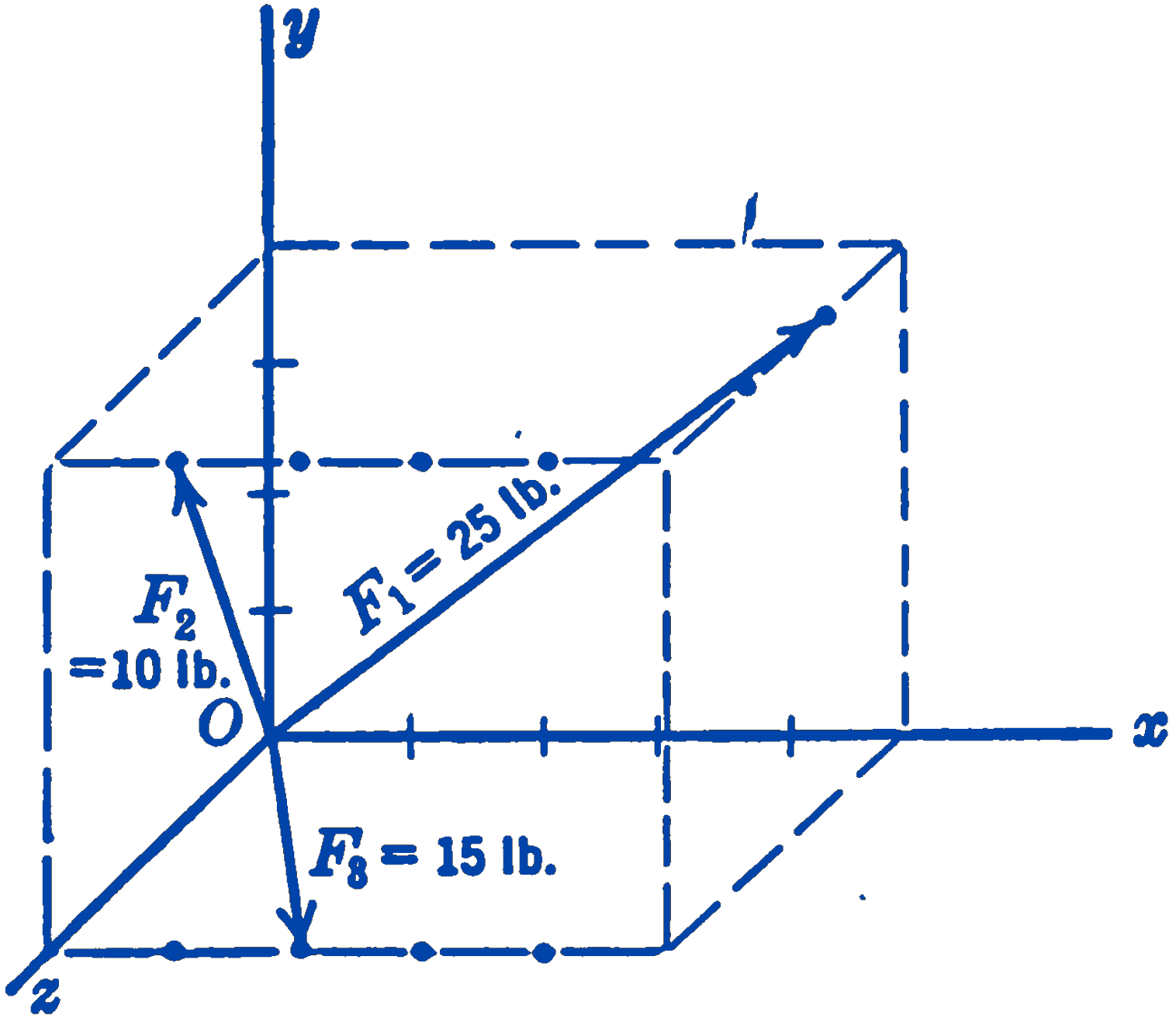
Answer
\(29.6\mathbf{i} + 23.3\mathbf{j} + 22.2\mathbf{k}\)
6. Show that a general system of forces all of which lie in one plane can be reduced either to a single force or a single couple.
7. Show that the condition that a general non-coplanar force system will reduce to a single force or a single couple is: \[ R_xC_x + R_yC_y + R_zC_z = 0 \] From this condition show that a general parallel system or a general coplanar system can be reduced to either a single force or a single couple.
8. Show that a force and a couple can always be resolved into a force and a couple whose vector is parallel to the force vector. Show that in this case the couple has its smallest possible value.
9. Find the resultant of the forces shown in the diagram.
Answer
\(268\ \mathrm{lb}\); \(1414\ \mathrm{ft}\cdot\mathrm{lb}\)
10. Determine the resultant of the forces shown in the diagram. Find a single force through the point \(A\) and a couple which will together be equivalent to the given system.
Answer
\(160\ \mathrm{lb}\); \(-179\ \mathrm{ft}\cdot\mathrm{lb}\)
11. Replace the three forces shown in the figure by a single force acting through the origin and a couple.
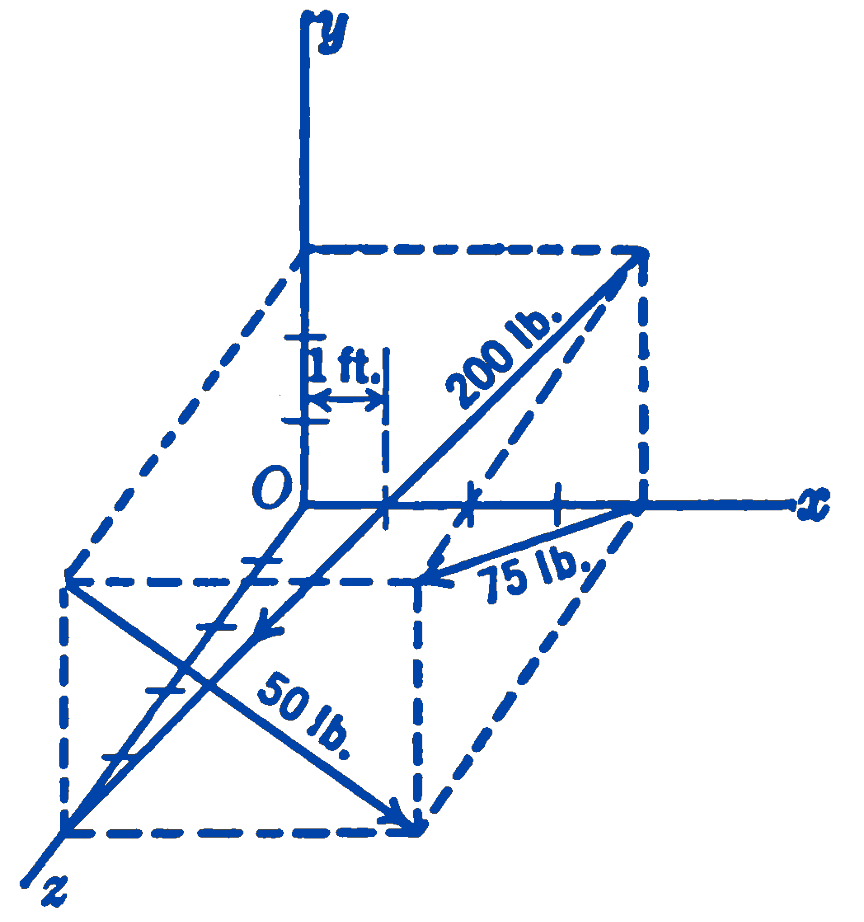
Answer
\(200(-0.565\mathbf{i} - 0.424\mathbf{j} + 0.707\mathbf{k})\)
12. The three forces shown in the figure are \(P\), \(2P\), and \(3P\) as indicated. State the algebraic relationship between the dimensions \(x_1\), \(y_1\), and \(z_1\) so that a single force may be the equivalent of the given forces.
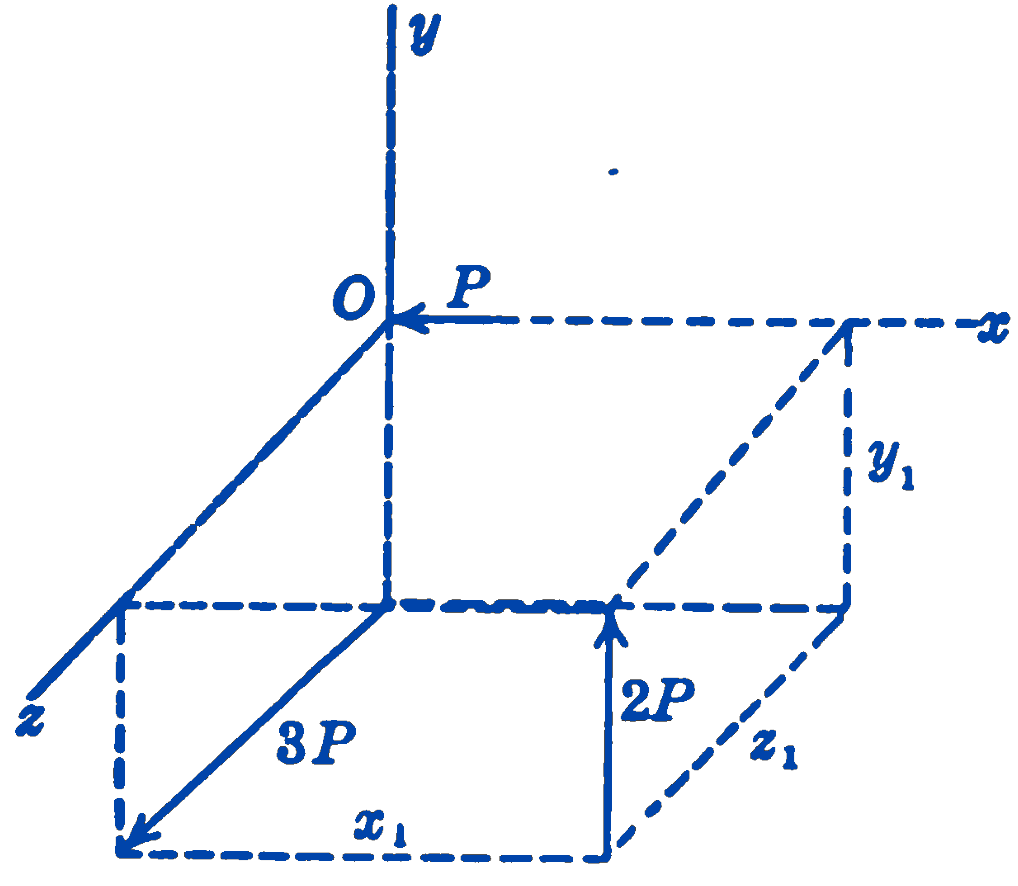
Answer
\(6x_1 + 3y_1 + 2z_1 = 0\)