From the preceding discussion it is seen that the methods of treating a system of given forces are relatively straightforward. The problems which confront the engineer or physicist, however, usually come in the form of some physical situation, so that the first step is to determine the system of forces which will represent the physical situation correctly. The application of the principles of statics to the forces of a system can often be reduced to a routine procedure. A more difficult problem is that of deciding which forces should be included in a particular system in order to arrive at a desired result. Skill in the manipulation of force systems will not suffice to solve the physical problem unless the forces which are equivalent to the given physical situation are included in the problem. On the other hand, once the true force picture is set up, the solutions practically always can be obtained by conventional methods which though they may involve extensive labor, ordinarily will require no great amount of ingenuity. The transition from a physical situation to a statement of the forces involved is the important first step in the solution of a problem.
Although the steps involved in recognizing the forces which must be included are not exactly the same for all problems, there are certain general principles which can be observed. The most important principle is that one must always distinguish between the particular mechanical system which is being investigated and the remainder of the universe. The process of the isolation of one particular portion of the universe, for purposes of a particular problem, is one of the central concepts in mechanics.
In order to isolate correctly a mechanical system, it is necessary to make a clear distinction between forces which are external to the system, and those which are internal. An external force is a force exerted on a system or some part of a system by a body outside of the system. An internal force is exerted on one part of the system by some other part of the same system. A particular force, of course, may be at the same time an internal force so far as one system is concerned, and an external force so far as another system is concerned.
Consider the two blocks of weight \(W_1\) and \(W_2\) as shown in Fig. 1a. In Fig. 1b the two blocks together have been considered as the mechanical system which is to be isolated, and a diagram has been drawn showing all of the external forces acting on the system. Such a diagram is called a free-body diagram.

The preparation of a free-body diagram should be the first step in every mechanics problem.
The purpose of the free-body diagram is to indicate that portion of the physical arrangement which is isolated as a mechanical system. The external forces acting on this system are the weights of the blocks \(W_1\) and \(W_2\), and the force \(N\) exerted on the system by the supporting plane. The force between the two blocks would in this system be an internal force and hence would not appear in the free-body diagram.
In Fig. 1c the upper block alone has been isolated as a mechanical system, and the free-body diagram has been drawn. In this system the external forces acting are the weight of the block \(W_1\) and the force \(N_1\) exerted on the block \(W_1\) by the block \(W_2\). In this case the force \(N_1\) is an external force so far as the system shown in (c) is concerned, but an internal force so far as the system of (b) is concerned.
The system which is selected for isolation need not follow the physical boundaries of the elements concerned, as it does in the example of Fig. 1. The free-body diagram may include only one portion of a body, as in the case shown in Fig. 2.
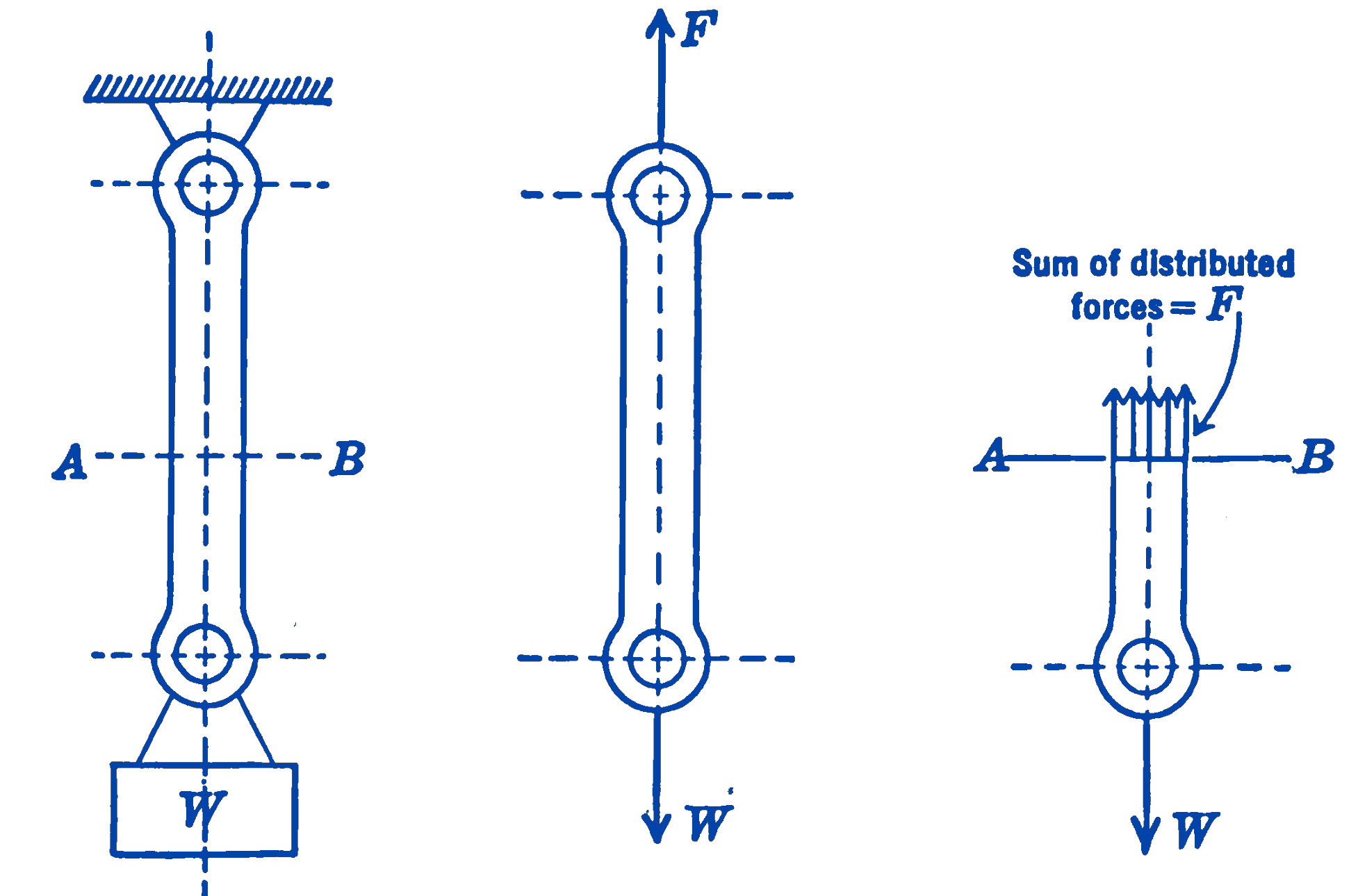
Fig. 2b is the free-body diagram of the tension link shown in Fig. 2a. The weight of the link has been assumed to be negligible compared to the weight \(W\). In Fig. 2c we imagine that the link has been cut at the section \(A-B\), and we draw a free-body diagram of the lower portion of the link. The force that each element of the upper portion exerts on the corresponding element of the lower portion is thus shown as a uniformly distributed system of forces over the upper section of the bar. The internal forces in the bar, which did not appear in Fig. 2b, are external forces for the section of the bar shown in Fig. 2c. It is apparent that such an imaginary cut must always be made if it is desired to study the internal forces in a body.
The question of precisely what should be included in the free-body diagram cannot be answered in general, and it is at this point that the ingenuity of the investigator must show itself. The unknown forces which are to be determined must appear, however, as external forces in some free-body diagram. For any type of force system there is a maximum number of equations which can be written, and hence a maximum number of unknown forces which can be determined. Frequently it will be found that the free-body diagram which will show the desired forces as external forces will involve so many unknown forces that no solution will be possible. In this event it may be necessary to begin the problem by considering some other free-body diagram, from which some of the unknowns may be determined.
It is of particular importance that all of the external forces acting upon the system be shown in the free-body diagram. There is sometimes a tendency to assume that certain forces, such as gravity forces, are so obvious that it is not necessary to take the time to put them down on the free-body diagram. Such practices inevitably lead, sooner or later, to the omission of such forces from consideration. Every force, no matter how obvious, should be included in the free-body diagram unless one of the assumptions or conditions of the problem is that the force is equal to zero. Even in such a case it is well to include the force, and then to write the statement that the force is equal to zero, since other conditions may exist under which the force cannot be neglected.
In considering the forces which may act upon a body, it should be noted that any point at which the body makes contact with another body is a point at which a force may exist. It may be possible, from other data given in the problem, to determine the direction of the force at the point. For example, the direction of the force which acts at a frictionless support is normal to the surfaces in contact. A second instance in which the directions can be found easily is that of a system in equilibrium under the action of only two forces. Since two forces can be in equilibrium only if they are equal in magnitude, opposite in direction, and lie along the same line of action, they must have the same direction as the line joining their points of application. This means that the forces acting at the ends of such members as cables and connecting rods have the direction of the cable or connecting rod, providing that the weight of the member is negligible. It must also be kept in mind that forces may exist without physical contact between bodies, as in the case of gravitational, electromagnetic, or electrostatic forces.
Example 1.
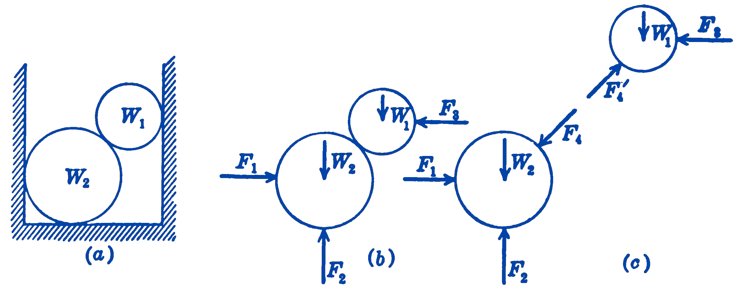
- Two smooth cylinders are shown (Fig. 3) resting in a smooth trough.
- A free-body diagram of the two cylinders considered as one body is shown in part (b). Since all of the surfaces are frictionless, the forces between surfaces in contact are normal to the surface. Note that the forces between the two cylinders are internal forces, so far as the system consisting of the two cylinders is concerned, so that these forces do not appear on the free-body diagram.
- In part (c) are shown the two free-body diagrams for the two cylinders, each considered as a separate mechanical system. In this case, considering either cylinder alone as a free-body diagram, the force exerted by the other cylinder becomes an external force in that system.
Example 2.
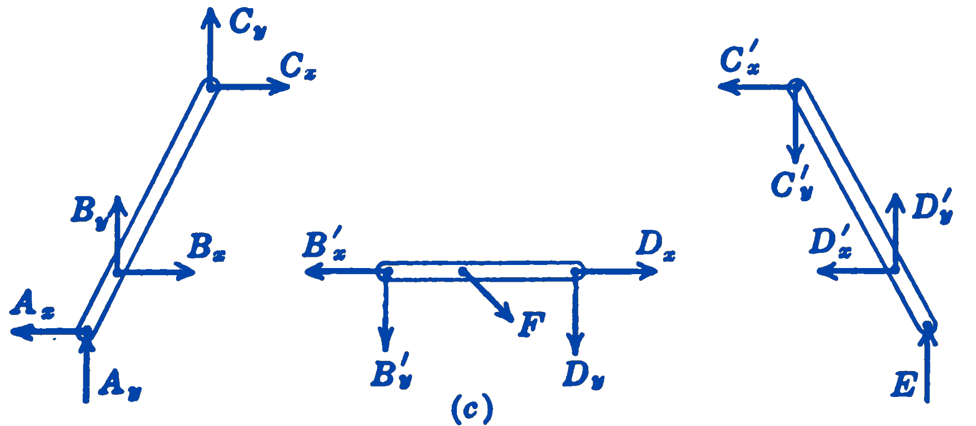
- A load \(F\) is applied to a rigid pinned framework as shown in Fig. 4a. The end of the member \(CE\) rests on frictionless rollers on a horizontal plane. The weights of the members are small compared to the other forces acting and may be neglected.
- In (b) is shown a free-body diagram of the whole structure. Since the rollers at \(E\) are frictionless, the force exerted on the framework at \(E\) must be normal to the surface. At \(A\) the pin can transmit a force in any direction, hence the direction as well as the magnitude of the force is unknown. We represent the force at \(A\), therefore, by two unknown rectangular components \(A_x\) and \(A_y\).
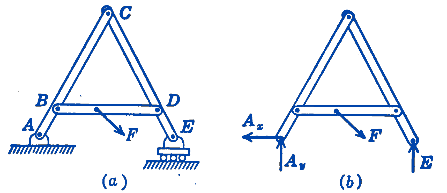
- Free-body diagrams of each of the three members making up the structure are shown in (c). At the pin connections both the magnitudes and directions of the forces are unknown, as indicated by the two unknown rectangular components of the force. The forces exerted between two members, which were internal forces in the system shown in (b) above, are now external forces so far as the separate members are concerned. These forces exist as equal and opposite pairs, and hence cancel out in (b).
Example 3.
- In Fig. 5a the elements of a simple band-type brake are shown. The brake drum rotates clockwise, a force \(P\) tightens the brake band on the drum and thus provides increased frictional forces between the band and drum as the force \(P\) tightens the brake band on the drum and thus provides increased frictional forces between the band and drum, forming a so-called self-energizing brake system.
- In (b) is shown a free-body diagram of a portion of the brake band subtended by the angle \(\theta\). The weight is small compared to the other forces acting and hence is neglected. If it is assumed that the brake band is perfectly flexible, i.e., can support no bending, the forces \(T\) and \(T + \Delta T\) will be tangent to the drum as shown. The frictional forces between the drum and the band are shown as a system of uniformly distributed forces tangent to the drum, and the reaction force between the drum and band is shown as a uniformly distributed system of normal forces.
- In this figure is shown the free-body diagram of a portion of the brake band subtended by an infinitesimal angle \(d\theta\). The uniformly distributed frictional forces have been replaced by their resultant \(dF\) and the uniformly distributed normal forces have been replaced by their resultant \(dN\).

Example 4.
- Fig. 6a shows a beam supported at two points and loaded by a vertical force \(P\) in such a way as to cause bending in a vertical plane.
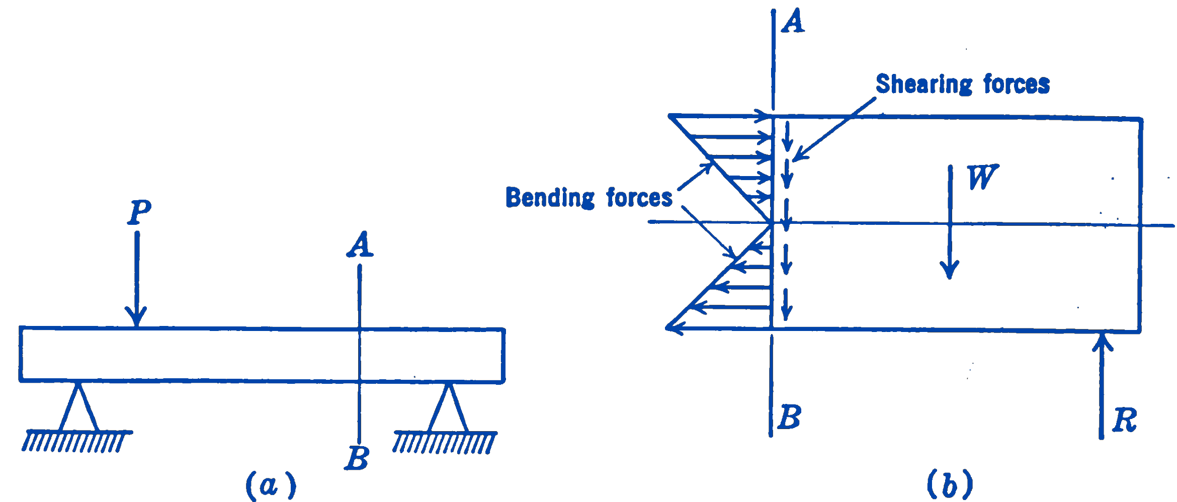
- In (b) is shown a free-body diagram of that portion of the beam to the right of the section \(A-B\). The vertical force exerted on the beam by the right support is shown as \(R\). The weight \(W\) of the portion of the beam to the right of the section \(A-B\) is shown acting at the center of gravity of the element. The forces exerted on this section of the beam by the left section, which we imagine to have been removed, are shown as two systems of forces, a system of horizontal forces due to bending in the beam, and a system of vertical forces due to shearing action. Neither of these two systems of forces is uniformly distributed. As we shall find out later by analyzing the problem, the bending forces will be in tension at the lower edge of the beam, compression at the upper edge of the beam, and will pass through zero at some intermediate section. The shearing forces will be zero at the top and bottom edges of the beam and will be maximum at some intermediate position. All that we do in the present free-body diagram is to indicate the presence of forces having unknown magnitudes and distributions. The particular form of the forces shown in the figure could not be determined without further analysis.
Example 5.
- Fig. 7a shows a section of a thick-walled tube subjected to an internal pressure \(p\).
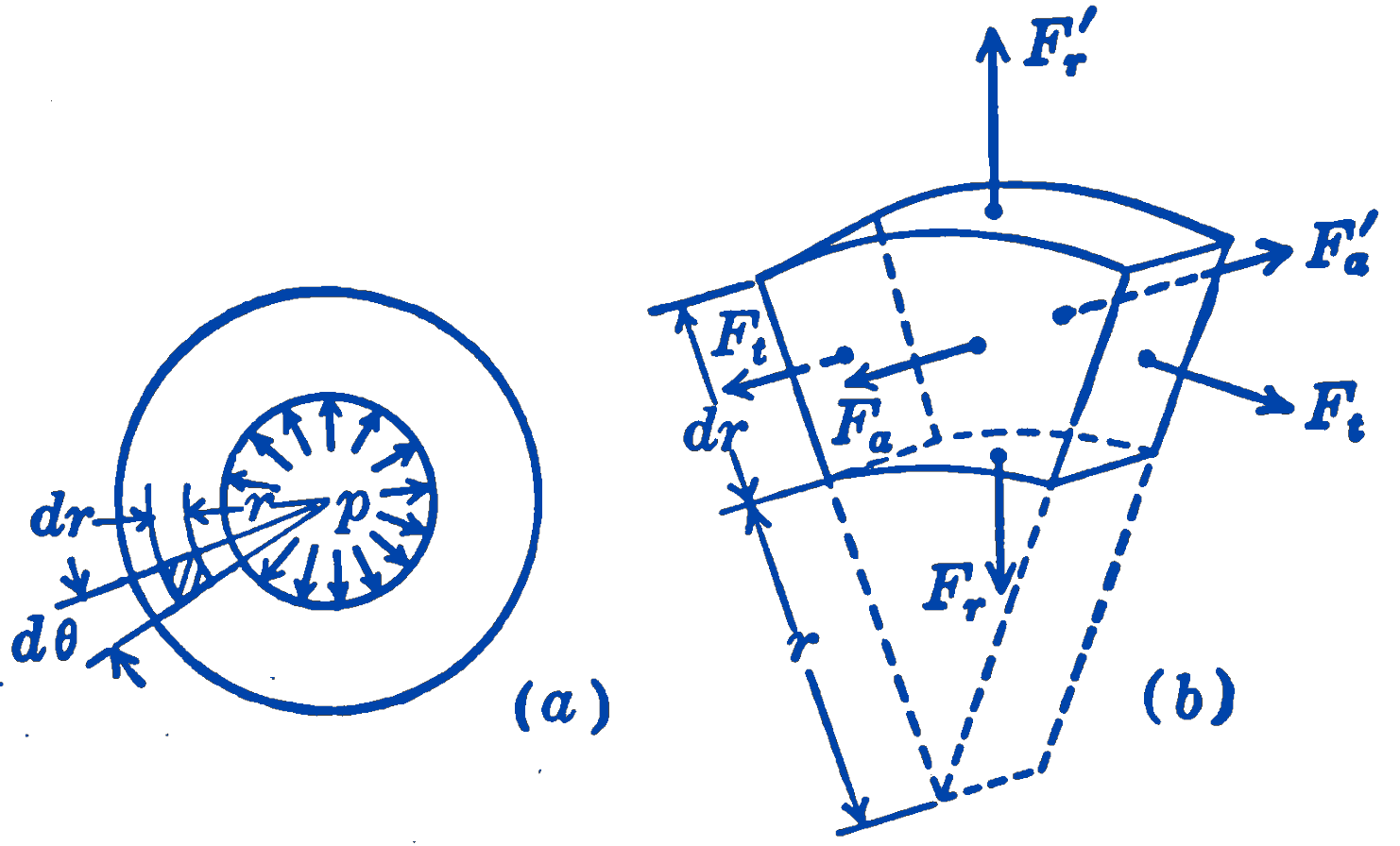
- Fig. 7b shows the free-body diagram of the very small element of the body shaded in (a). All six faces of this element are acted upon by forces which may be considered as uniformly distributed over the infinitesimally small areas of the faces. These uniformly distributed forces have been replaced by their resultant forces, acting at the centroid of the faces of the element. The weight of the element has been assumed to be very small compared with the other forces acting on the system.
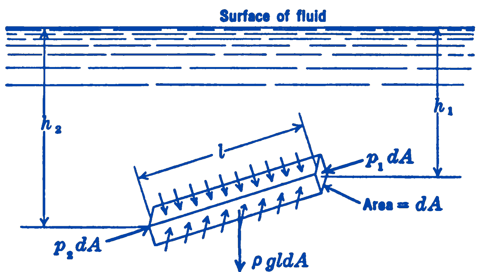
Example 6. Figure 8 shows a free-body diagram of a rectangular prism of fluid located at some distance below the surface of the fluid. The infinitesimal cross-section area of the prism is \(dA\), and the length of the prism is \(l\). On each face of the prism, the force acting will be equal to the pressure times the area. The gravity force will be the volume of the prism times the specific weight.
Example 7.
- In Fig. 9a are shown the basic elements of the oil drop experiment by means of which Millikan determined the charge of the electron. The oil drop of weight \(W\) is shown in an electric field of intensity \(E\).
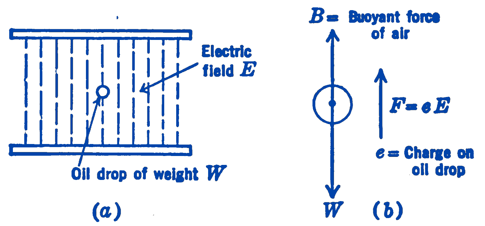
- A free-body diagram (b) of the oil drop is shown. The drop is in equilibrium under the action of the buoyant force of the air, the weight, and the force due to the presence of the charge in the electric field.
In all the examples given above, the forces acting on the system have been balanced, and hence the systems have been in equilibrium. The usefulness of the free-body diagram, however, is not limited to problems in statics only. In dynamics problems, where motions result from unbalanced force systems are studied, it is of the highest importance to have a clear picture of all the forces acting upon the system.
Some examples of free-body diagrams applied to dynamics problems follow:
Example 8.
- Figure 10a shows a schematic view of one cylinder of a reciprocating internal combustion engine.
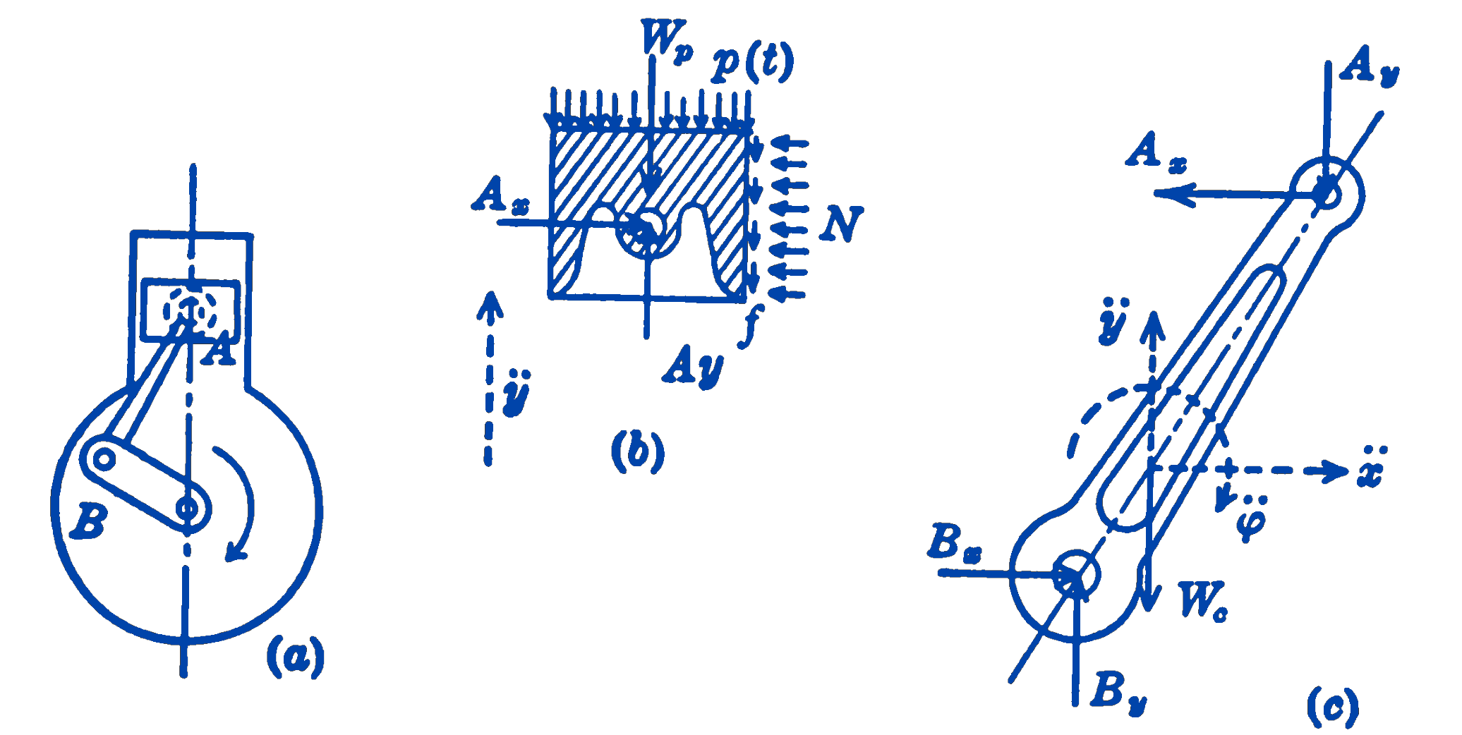
- Figure 10b is a free-body diagram of the piston \(A\) of the engine. The forces \(p(t)\), which are approximately uniformly distributed over the top of the piston, are the gas-pressure forces resulting from the explosion of the gas-air mixture above the piston. These forces vary with respect to time, hence they are indicated as functions of time. The force exerted by the connecting rod \(AB\) on the piston is unknown in both magnitude and direction, hence it is indicated in the diagram as two rectangular components \(A_x\) and \(A_y\). The forces exerted on the piston by the cylinder wall are shown approximately as two uniformly distributed systems of forces, normal forces \(N\), and frictional forces \(f\). The dotted vector indicates the direction of the acceleration of the piston. The weight of the piston \(W_p\) is shown acting at the c.g. of the piston.
- In this figure (c) a free-body diagram of the connecting rod \(AB\) of the engine is shown. The force exerted on the rod by the piston at \(A\) is shown as two rectangular components \(A_x\) and \(A_y\). These are, of course, equal and opposite to the forces exerted by the rod on the piston as shown in diagram (b) above. The forces exerted by the crankshaft on the lower end of the rod are shown as two unknown rectangular components \(B_x\) and \(B_y\). The weight of the connecting rod \(W_c\) is shown acting at the center of gravity of the rod. The dotted vectors indicate that there is an acceleration of the c.g. of magnitude \(\ddot{x}\) in the \(x\)-direction, of magnitude \(\ddot{y}\) in the \(y\)-direction, and an angular acceleration of magnitude \(\ddot{\varphi}\).
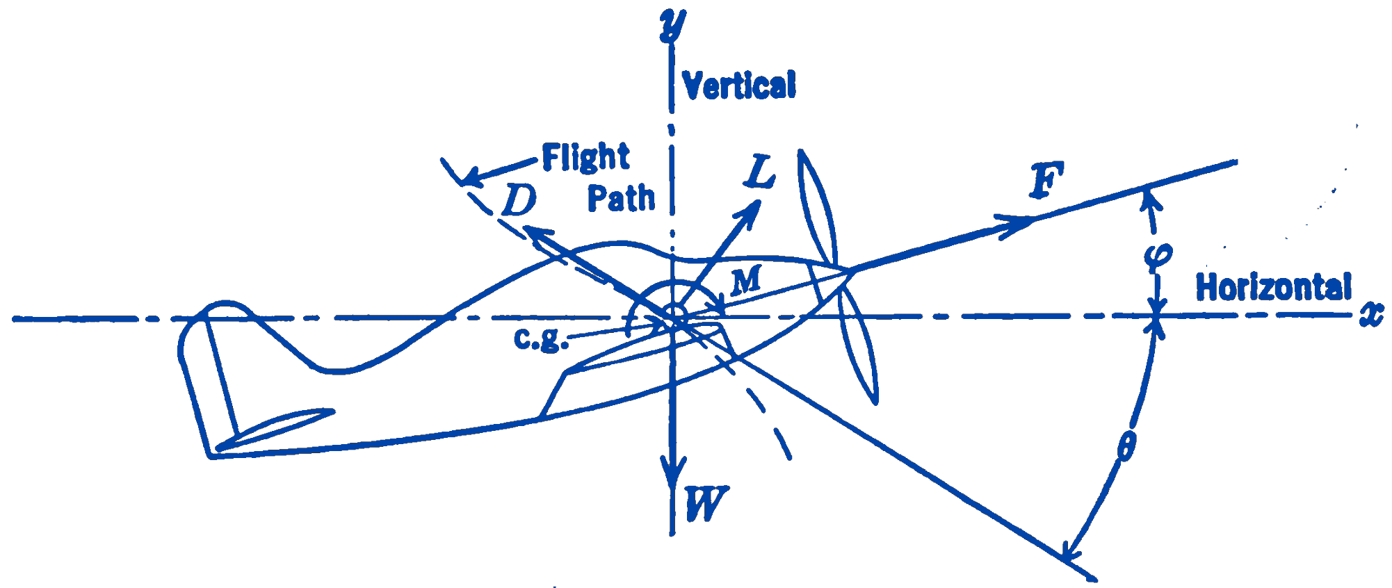
Example 9. Fig. 11 shows the free-body diagram of an airplane considered as a rigid body. The longitudinal axis of the airplane makes an angle \(\varphi\) with the horizontal, and the flight path makes an angle \(\theta\) with the horizontal as shown. The weight of the airplane \(W\) is shown acting at the center of gravity of the airplane. There is a lift force \(L\), perpendicular to the flight path, a drag force \(D\) tangent to the flight path, and a moment \(M\) which tends to pitch the airplane about an axis perpendicular to the paper. The force \(F\) is the propeller thrust.
1.14.1 Problems
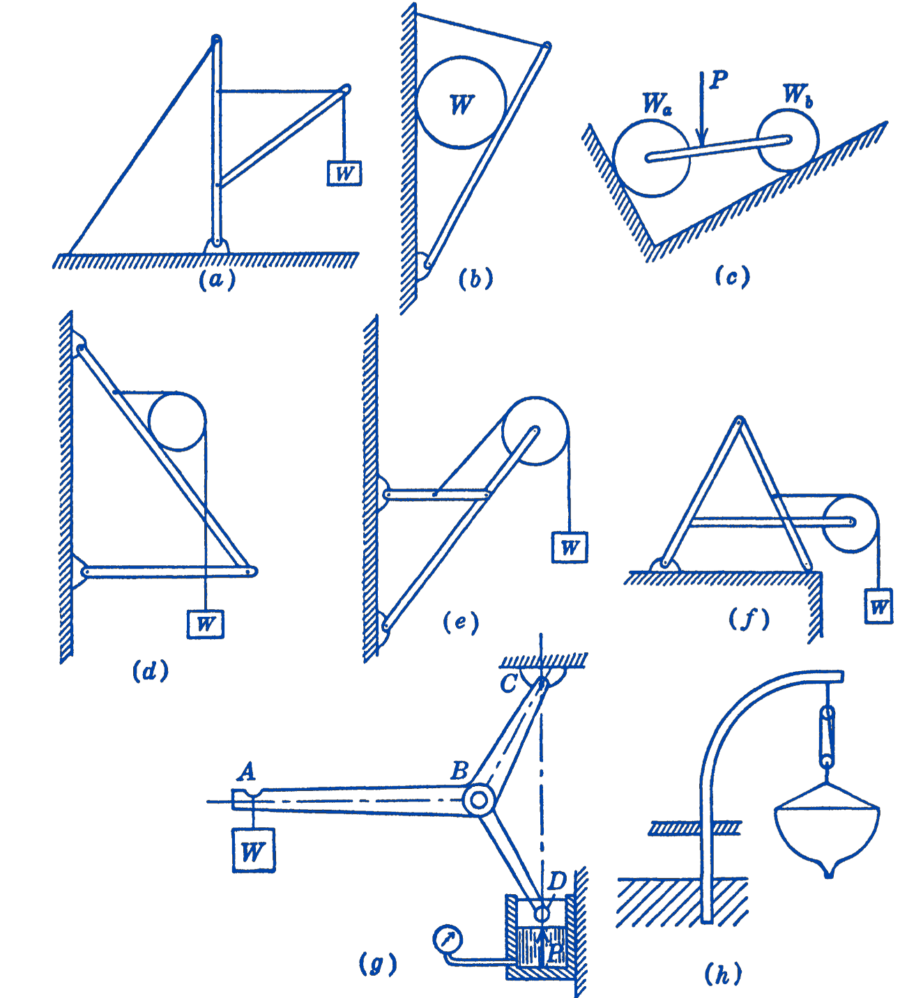
1. For each of the following structures , draw a free-body diagram of the complete structure , and for each of the members of the structure.
