We have seen above that the construction of a funicular polygon is equivalent to solving the moment equations. We shall now show the relationship between the funicular diagram and the moment of a force.
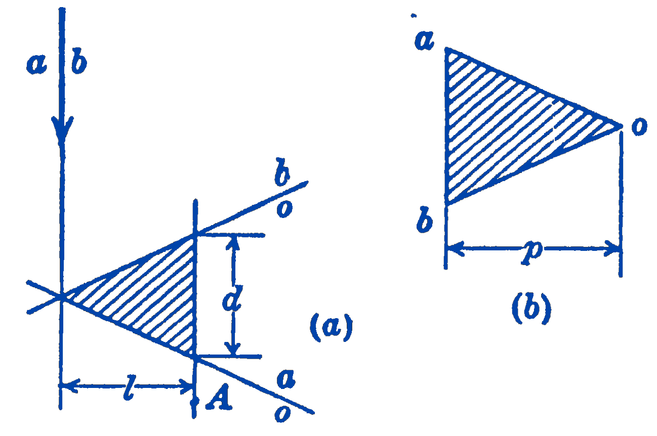
In Fig. 1a is shown a force (\(ab\)) as it appears in the funicular diagram. The force diagram for the same force is shown in Fig. 1b. In (a) are also shown the two strings \(ao\) and \(b o\) of the funicular diagram which are parallel to the rays \(ao\) and \(bo\) in the force diagram. Take any point \(A\) at a distance \(l\) from the force \((a b)\) and let the intercept of the funicular diagram which would be cut by a line through \(A\) parallel to \(a b\) be called \(d\). We further call the perpendicular distance between the pole \(O\) and the force \((a b)\) the pole distance, \(p\). Then, the two triangles which are shown shaded in Fig. 1 will be seen to be similar, and we have: \[ \begin{aligned} \frac{l}{p} & =\frac{d}{(a b)} \\ l(a b) & =p d \end{aligned} \] but \(l(a b)=\) the moment of the force (ab) about the point \(A\); therefore, we can say: The moment of a force about a point is equal to the pole distance times the intercept on the funicular diagram.

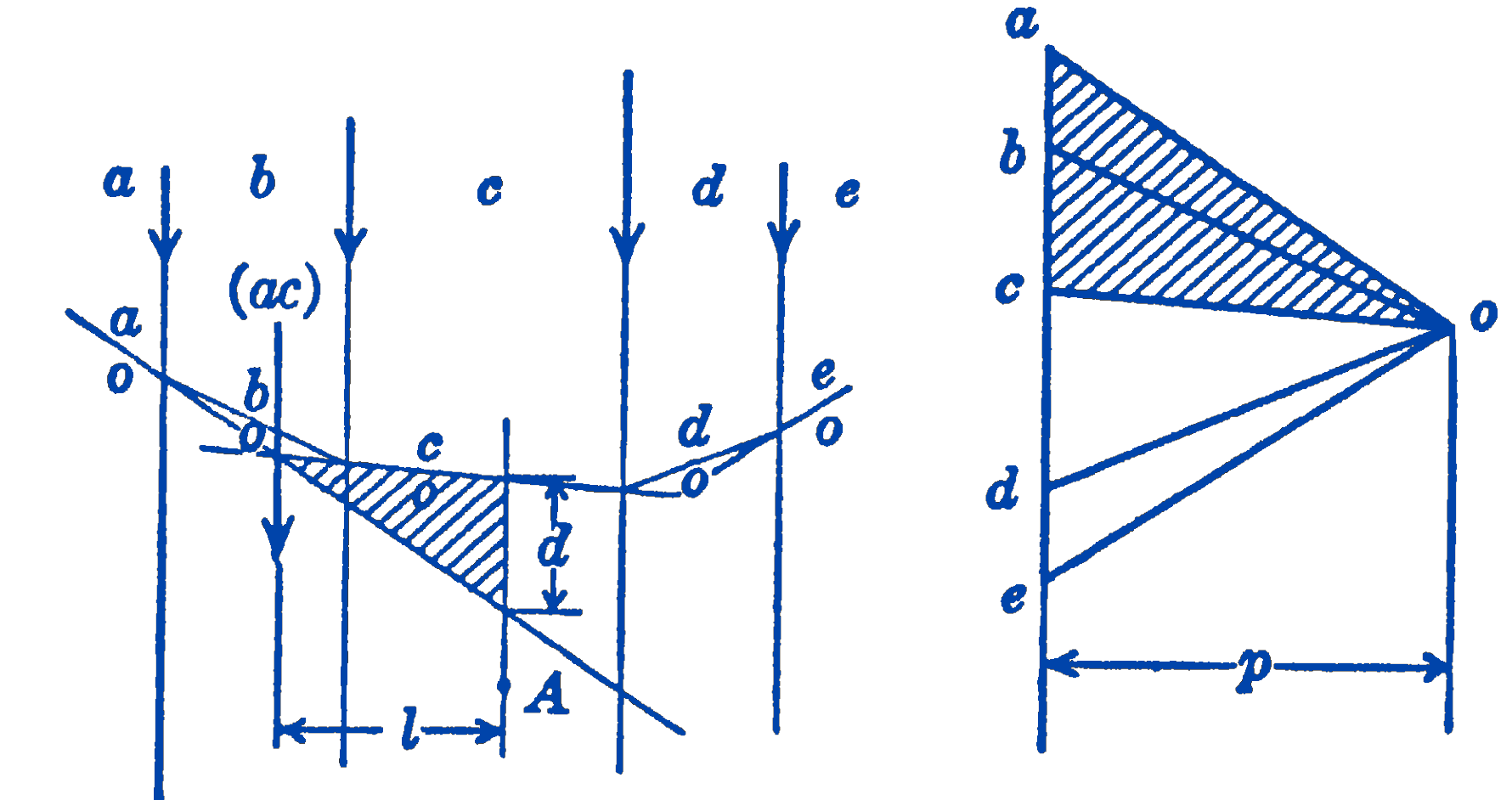
The chief value of this proposition may be seen in the case of a system of parallel forces, as shown in Fig. 2.

Suppose that we wish to find the sum of the moments of all of the forces to the left of the point \(A\) about the point \(A\). As before, we let \(d\) be the intercept on the funicular diagram of a line through \(A\) parallel to the forces of the system. The sum of the moments of the forces \((a b)\) and (\(b c)\) about the point \(A\) will be equal to the moment of the resultant of the two forces (\(ab\)) and (\(bc\)) about the point \(A\). This resultant is the force (\(ac\)), which acts at the position shown on the funicular diagram. Again noting that the shaded triangles shown in the funicular diagram and in the force diagram are similar, we have: \[ \begin{aligned} \frac{l}{p} & =\frac{d}{(a c)} \\ l(a c) & =p d \end{aligned} \] or the sum of the moments to the left of the point \(A\) is equal to the intercept in the funicular diagram times the pole distance.
It will be seen from Fig. 2 that this conclusion would be true for any position of the point \(A\) and for any number of forces.
In a number of engineering problems it is required that a diagram be prepared which will show, for a system of parallel forces, the sum of the moments of all of the forces to the left of a point for various positions of the point. It will be seen that the funicular diagram represents, to a scale depending on the pole distance \(p\), such a moment diagram. Funicular diagrams are much used, in this way, in the graphical determination of the deflections and critical speeds of shafts.
6.8.1 PROBLEMS
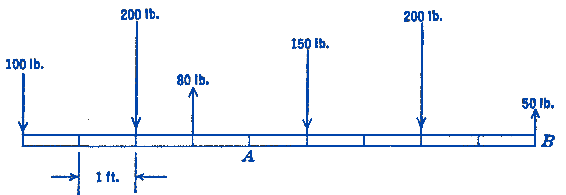
1. Find graphically the resultant moment about the point \(A\) and about the point \(B\) of the forces to the left of these points, for the system shown in the diagram. Check the moments about \(A\) analytically.

Answer
\(M_{\mathrm{A}}=720 \ \mathrm{ft}-\ \mathrm{lb} ;\) \(M_{\mathrm{B}}=2820 \ \mathrm{ft}\cdot\mathrm{lb}\)
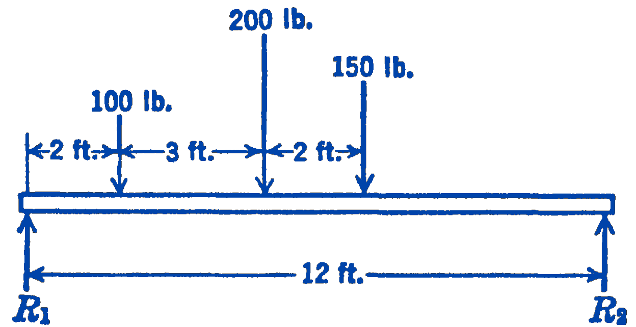
2. A beam loaded as shown in the diagram is supported at its two ends. Find graphically by means of a funicular diagram the point along the length of the beam about which the sum of the moments of all of the forces on one side of the point is a maximum.

Answer
5 ft from left end