One very common type of structure consists of straight members so connected together that they form a rigid framework. The members of such a framework are usually long, slender bars loaded in tension or compression. The meaning of the term “rigid framework” may be seen in Fig. 1.
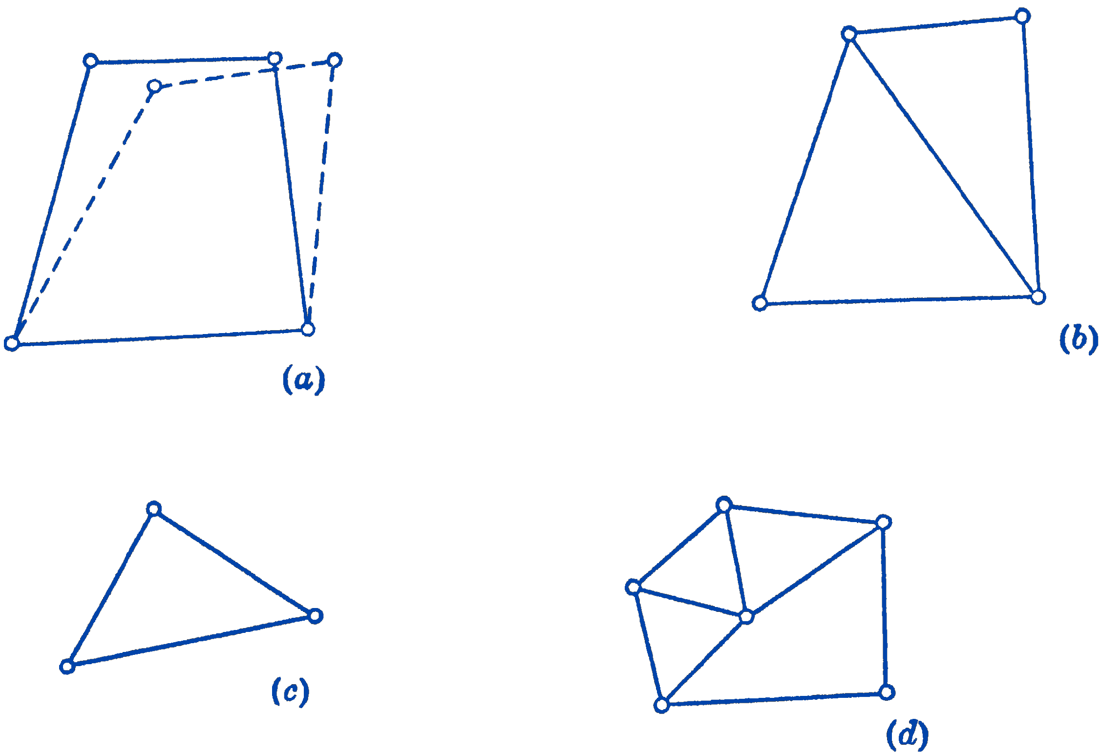
In Fig. 1a, a framework consisting of four bars pinned together at their ends is shown. It will be seen that such an arrangement is not a rigid framework, since the whole system can deform as shown by the dotted lines, without changing the dimensions of the members. This deformation could be prevented, however, by the addition of one more member as shown in Fig. 1b. The framework, which now consists of two triangular sections, will be seen to be rigid. The simplest rigid system is the triangular framework, Fig. 1c, and any complex system which is formed by triangular sections, as Fig. 1d, will also be a rigid framework.
For a rigid framework, there is a definite relationship between the number of members, \(m\), and the number of joints, \(j\). Suppose that one of the members of a planar framework is fixed with respect to a coordinate system. If the whole frame is to be rigid, then the remaining \((j-2)\) joints must have positions in this coordinate system which are determined by the given lengths of the members. Each of the \((j-2)\) joints has its two coordinates fixed by the intersection of two additional members. Since one bar is already fixed we have \((m-1)\) members left to locate the joints; hence: \[ \begin{aligned} \frac{(m-1)}{2} & =(j-2) \\ m & =2 j-3 \end{aligned} \]
This relationship is the necessary condition for a rigid planar framework. It is not, however, a sufficient condition, as the members may be so arranged that they do not contribute to the rigidity of the framework. This is illustrated in Fig. 2.
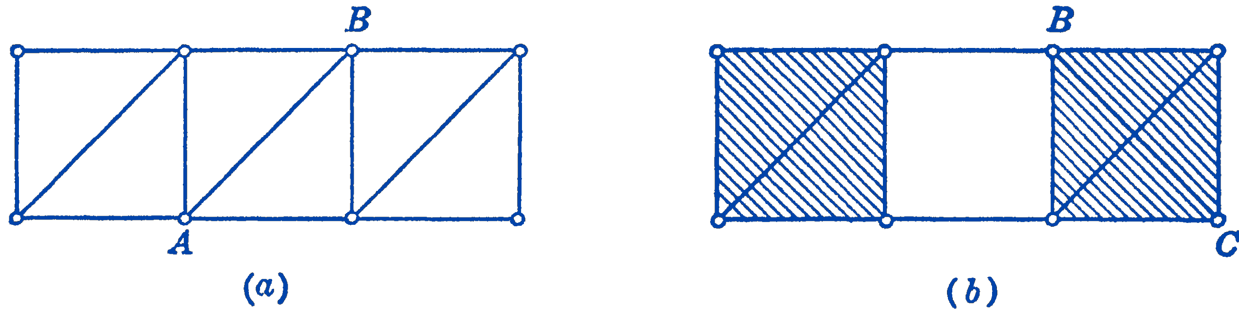
In Fig. 6-2a a rigid framework is shown which satisfies the above condition. By moving the member \(A B\) to the position \(B C\) in Fig. 6-2b, the frame becomes non-rigid, since the right-hand shaded section could be translated with respect to the left-hand shaded section. Thus the frame in (b) is non-rigid even with the same relationship between members and joints, since the bar \(B C\) is so placed that it does not maintain the complete constraint of the frame. If the necessary condition is fulfilled, however, one can usually easily tell by inspection whether the frame is rigid, or whether an exceptional condition such as illustrated above is present.
We next consider how to constrain a rigid frame in space by means of supporting members which will exert reactive forces upon the framework when it is loaded by a system of external forces. We shall suppose that the framework is loaded only by forces which lie in the plane of the frame, and hence we need only consider constraint of the frame in a plane.
Following the same line of reasoning as used in Chapter: The Equilibrium of Force System to establish the condition of complete constraint of a body in space, we find that to constrain a body completely in a plane the equivalent of three non-parallel, non-concurrent forces must be used, as shown in Fig. 3a.
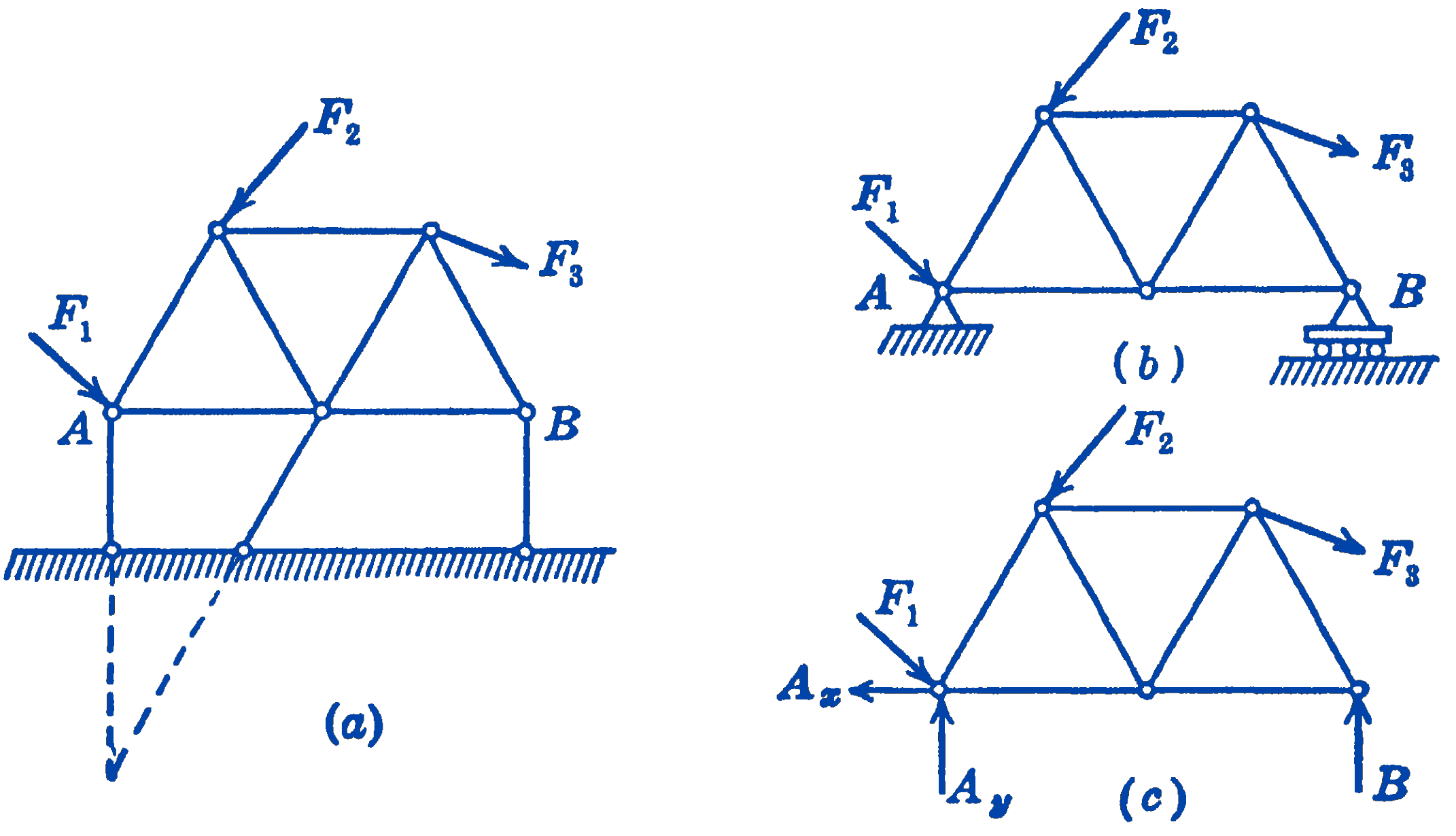
A common means of accomplishing this constraint is shown in Fig. 3b, where one end of the frame is supported by a pin which can exert a reactive force in any direction in the plane, while the other end is supported in such a way that a vertical reactive force only can be developed. These supports are represented by the three reactive forces \(A_{x}, A_{y}\), and \(B\), in the free-body diagram of Fig. 3c.
We now suppose that the framework which is constrained by its supports is loaded by a system of external forces (as \(F_{1}, F_{2}\), and \(F_{3}\) in Fig. 3), and we investigate the problem of finding the unknown forces in the members and the unknown reactions at the supports. The total number of unknown elements will be the \((2 j-3)\) axial forces in the members, plus the three reaction forces, so that the total number of unknown forces is (2j). The forces acting at each joint of the structure form a concurrent, coplanar force system, for which two independent equations can be written. Thus, the total number of independent equations that ćan be written for the whole system is (\(2 j\)), which will just suffice for the determination of the (\(2j\)) unknowns. Such a system is said to be statically determinate, and the equilibrium equations alone will suffice for the solution of all of the unknown forces in the system.
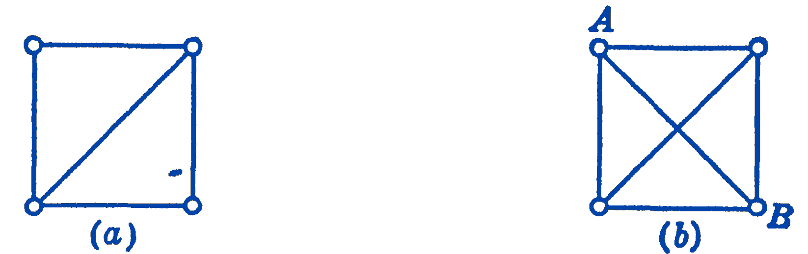
It is possible, however, that there may be more members in a system than are required for rigidity. If, for example, in Fig. 4b we add the member \(A B\) to the already rigid frame of Fig. 4a, we will have more unknown forces than we have equations.
Such additional members are called redundant members, and their presence makes the problem statically indeterminate, since there will not be enough equilibrium equations to solve for the unknown forces. To solve such statically indeterminate problems the deformations of the members must be taken into account, and hence the theory of elasticity must be brought into the problem. We shall confine ourselves, in the present chapter, to statically determinate systems.