A commonly encountered structural element is a flexible cable or chain, suspended from its two ends and loaded by a system of vertical forces. By a flexible cable we mean a cable that is capable of supporting only a tension force which at any point is tangent to the curve assumed by the cable. The two most common types of loading are a load which is uniformly distributed across the horizontal span of the cable, and a vertical load which is uniformly distributed along the length of the cable. The first case is encountered in suspension bridges where the weight of the horizontally supported structure may be large compared to the weight of the suspension cables, whereas the second type of loading is that encountered by electric transmission lines.
We shall first see how far we can carry the analysis for a flexible cable whose ends are supported at different heights, and which is loaded by a system of vertical forces that vary in any given manner, as shown in Fig. 1a. We shall neglect the stretching of the cable under the load by assuming that the cable is inextensible.
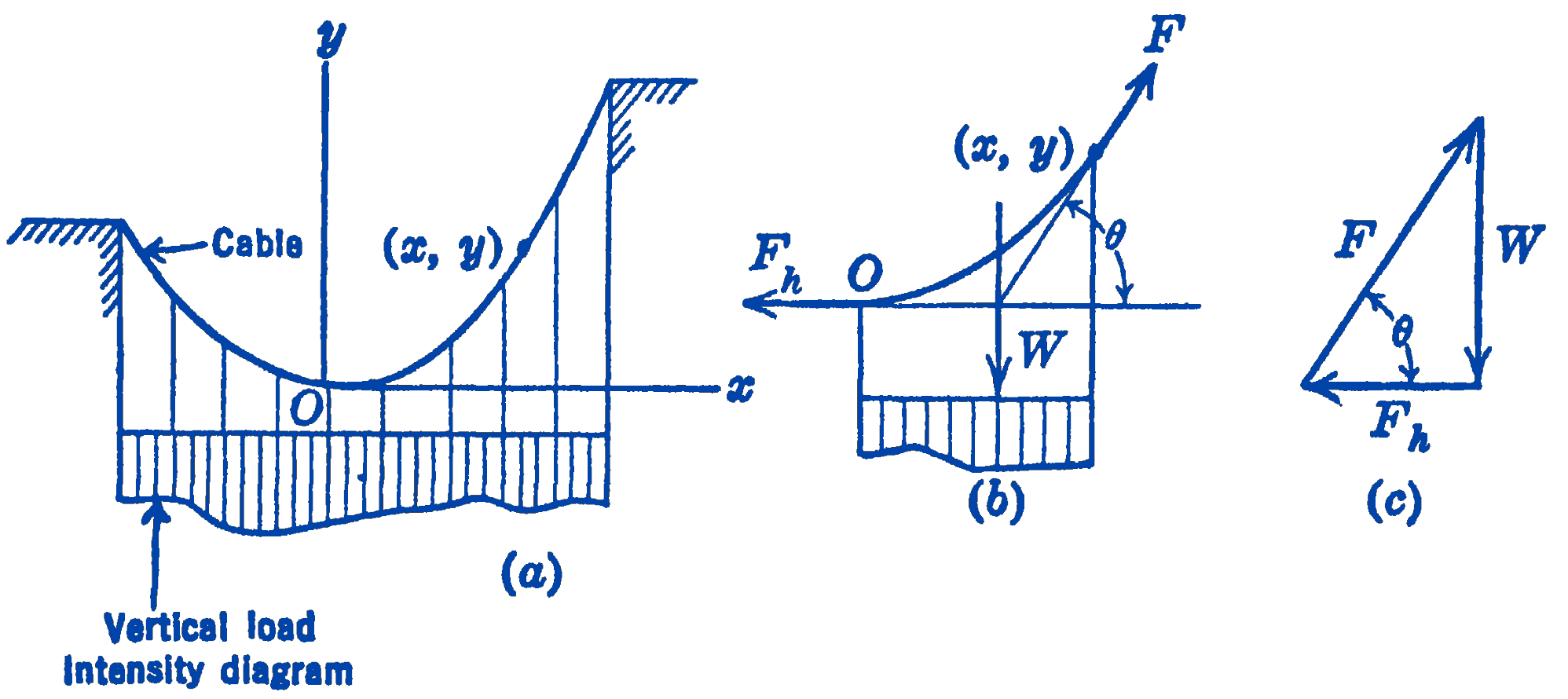
We fix the origin of an \(x y\) coordinate system, which is in the plane of the cable, at the lowest point of the cable. We then draw a free-body diagram of the portion of the cable between this lowest point \(O\), at which the cable has a horizontal tangent, and any point \(x, y\) on the cable. The forces acting on the cable are the horizontal force \(F_{h}\) at \(O\), the tangential force \(F\) at the point \(x, y\) and the force \(W\), which is the portion of the load acting upon the length of cable from \(O\) to \(x, y\) and which includes the weight of the cable. This force \(W\) acts through the center of gravity of the load intensity diagram, as shown in Fig. 1b.
We now note that we have a system of three forces in equilibrium, so that they must be concurrent. Hence, if the shape of the load intensity diagram is known, the position of \(W\) will be known, and the direction of the tangential force \(F\) will be fixed. Since the direction of the tangent to the cable at any point could thus be determined, the shape of the curve assumed by the cable could be found.
If we let \(\theta\) be the angle made by the tangent to the curve at the point \(x, y\) with the horizontal, we have: \[ \frac{d y}{d x}=\tan \theta \] Also from the force diagram of Fig. 1c we note that: \[ \tan \theta=\frac{W}{F_{h}} \] so that the differential equation describing the shape of the suspended cable is: \[ \bbox [5px,border:1px #f2f2f2;background-color:#f2f2f2]{\frac{d y}{d x}=\frac{W}{F_{h}}} \] For the two simple load distributions mentioned above, this differential equation can be solved analytically, and the equation of the suspended cable can be found.