When a body floats in equilibrium in a fluid, the buoyant force of the fluid is just equal to the gravity force on the body. A floating body thus submerges until an amount of fluid is displaced which weighs just as much as the body.
The question as to whether or not this position of equilibrium is stable, is of great importance in the design of ships. It will be seen at once that such floating equilibrium positions are stable so far as vertical displacements are concerned. If, for example, the body should be moved slightly downward from the equilibrium position into the fluid, more fluid will be displaced and the upward buoyant force will increase, thus tending to move the body back to the equilibrium position. Similarly, if the body is raised, the decrease in buoyant force will result in a net downward force which will tend to move the body back into the equilibrium position. So far as horizontal movements are concerned, the equilibrium will be seen to be neutral, since the forces of the system are not changed during such displacements. The question of stability of the body in the presence of angular motions, however, cannot be settled so quickly, and requires further consideration.
In Fig. 1a is shown the cross section of a ship floating in the water. The center of gravity of the ship is at the point \(G\), and the center of gravity of the displaced fluid, shown shaded, is at the point \(B\), in the equilibrium position. The point of application of the buoyant force \(F_{B}\) is at the point \(B\). If now, we rotate the ship about a longitudinal axis through a small angle \(\phi\), the point \(B\) will assume some new position, such as \(B^{\prime}\) or \(B^{\prime \prime}\) in Fig. 1b and 1c.
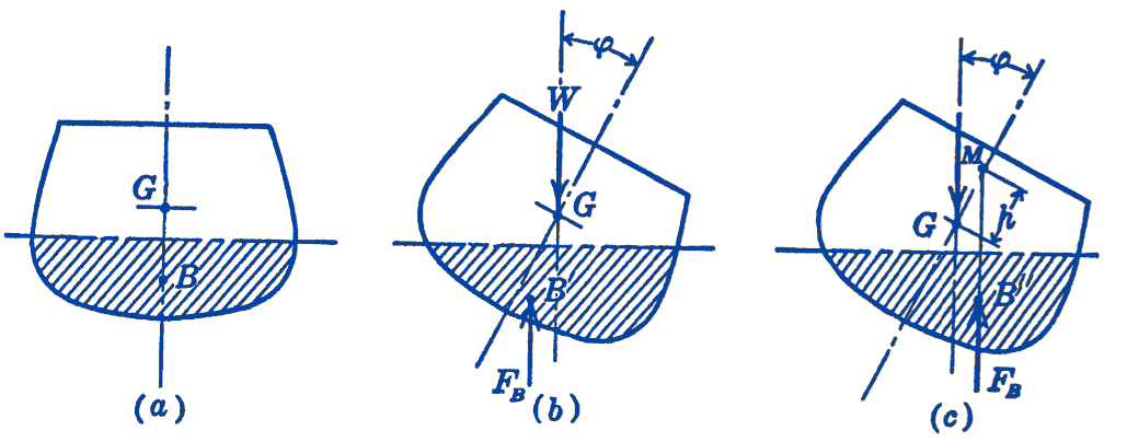
Depending upon the position of this point \(B\), two different situations will exist. In Fig. 1b it will be seen that for the position of \(B^{\prime}\) shown there, the forces \(F_{B}\) and \(W\) form a couple which has such a direction that it tends to increase the angle of roll. The equilibrium is therefore in this case unstable. In Fig. 1c, on the other hand, the position of \(B^{\prime \prime}\) is such that a couple is formed which tends to return the ship to the equilibrium position, and hence the equilibrium position is, in this case, stable. Since the position of the points \(B^{\prime}\) and \(B^{\prime \prime}\) evidently depends upon the geometry of the system, it is clear that for each floating body an investigation of such stability conditions must be made.
Referring to Fig. 1c we observe that the line of action of the buoyant force \(F_{B}\) intersects the line through the points \(G\) and \(B\) at the point \(M\). This point is called the metacenter of the body, and the distance \(h\) between the metacenter and the center of gravity is called the metacentric height. It will be seen that if the metacenter is above the center of gravity, the equilibrium is stable, whereas, if the metacenter is below the center of gravity, the equilibrium is unstable.
The metacentric height can easily be determined experimentally for any particular ship. Suppose that for the ship shown in Fig. 1 we find experimentally that a weight \(w\) placed a distance \(b\) from the centerline of the ship causes the ship to roll through some small angle \(\phi\). From the equilibrium conditions we would have: \[ \begin{gathered} w b \cos \phi=W h \sin \phi \\ \text { for } \phi \text { small; } \cos \phi \approx 1, \sin \phi \approx \phi \end{gathered} \] Therefore, \[ h=\frac{w b}{W \phi}. \]
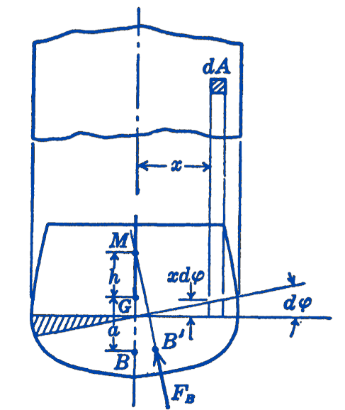
The metacentric height can also be computed, as we shall now show. In Fig. 2 suppose that the surface of the water is rotated through an infinitesimal angle \(d \phi\), which is equivalent to having the ship rotate through the angle \(d \phi\). As a result of this rotation the center of buoyancy will shift from \(B\) to \(B^{\prime}\) and this shift can be computed by taking moments of the volumes about the point \(B\), calling the displaced volume \(V\). \[ \begin{aligned} (V)(0)+\int_{A}(x d \phi) d A \cdot x & =(V)\left(B B^{\prime}\right) \\ d \phi \int_{A} x^{2} d A & =(V)\left(B B^{\prime}\right) \\ B B^{\prime} & =\frac{d \phi}{V} \int_{A} x^{2} d A \end{aligned} \] The integral \(\displaystyle \int_{A} x^{2} d A\) is summed up over the whole water-line area of the ship. Denoting this moment of inertia of the water-line area of the ship by \(I\), we have: \[ B B^{\prime}=\frac{d \phi}{V} I \] Also from Fig. 2, we have: \[ BB'=(h+a)\,d\phi \] Thus: \[ \begin{aligned} & (h+a) d \phi=\frac{I}{V} d \phi, \text { and since } V=\frac{W}{\gamma_{p}} \end{aligned} \] \[ h=\frac{\gamma I}{W}-a \]
Example. A rectangular parallelepiped having a square base floats in a fluid with the square base horizontal. The material of the block is homogeneous and has a specific weight \(\gamma\). What is the maximum height of the block consistent with rolling stability?
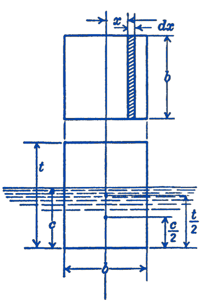
Solution. We find the maximum height \(t\), which is consistent with stability, by equating the metacentric height to zero. \[ h=\frac{\gamma_{F}}{W}-a=0 \] \(a\) is the distance between the center of gravity of the body and the center of buoyancy, and hence is equal to: \[ a=\frac{t}{2}-\frac{c}{2}=\frac{1}{2}(t-c) \] If \(\gamma_{F}\) is the specific weight of the fluid, we have: \[ \begin{aligned} b^{2} t \gamma & =b^{2} c \gamma_{F} \\ c & =\frac{\gamma}{\gamma_{F}} t \end{aligned} \] hence \[ a=\frac{1}{2}\left(t-\frac{\gamma}{\gamma_{F}} t\right)=\frac{t}{2}\left(1-\frac{\gamma}{\gamma_{F}}\right) \] To evaluate the moment of inertia \(I\), we indicate the element of area of the water-line area as \(b d x\), the integral becomes: \[ \begin{gathered} I=2 b \int_{0}^{\frac{b}{2}} x^{2} d x=\left.2 b\left(\frac{x^{3}}{3}\right)\right|_{0} ^{\frac{b}{2}} \\ I=\frac{b^{4}}{12} \end{gathered} \] Thus we have: \[ \frac{t}{2}\left(1-\frac{\gamma}{\gamma_{F}}\right) =\frac{\gamma_{F} b^{4}}{12 b^{2} t \gamma} \]
\[ t =b \sqrt{\frac{1}{6\left(1-\dfrac{\gamma}{\gamma_{F}}\right)\left(\dfrac{\gamma}{\gamma_{F}}\right)}} \] As a specific example, take a block of wood which weighs \(40\ \mathrm{lb}\) per cu ft and float it in water having a weight of \(62.4\ \mathrm{lb}\) per \(\mathrm{cu} \mathrm{ft}\). Then the maximum height consistent with rolling stability is: \[ t=b \sqrt{\frac{1}{6\left(1-\frac{40}{62.4}\right)\left(\frac{40}{62.4}\right)}}=0.851 b \] e.g., if \(b=4\ \mathrm{in}\), \(t_\max=3.4\ \mathrm{in}\).
4.15.1 PROBLEMS
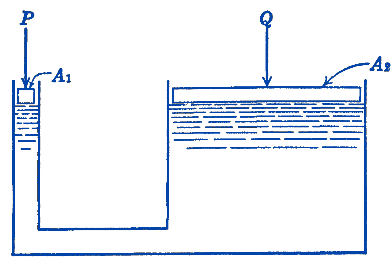
1. Find the equilibrium relationship between the loads \(P\) and \(Q\) on the hydraulic press shown in the diagram. The areas of the two pistons are \(A_{1}\) and \(A_{2}\), and the weights of the pistons may be neglected.
2. The supporting members \(A B\) for the framed dam shown in the figure are placed \(5 \mathrm{ft}\) apart along the length of the dam. What is the force in \(A B\) ?
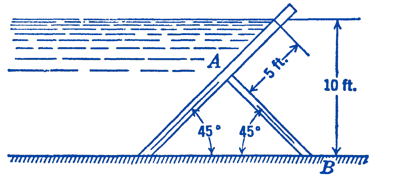
Answer
\(11,500 \ \mathrm{lb}\)
3. A sluice-gate is supported by a force \(F\) as shown in the figure. What is the magnitude of \(F\) for the water levels shown?
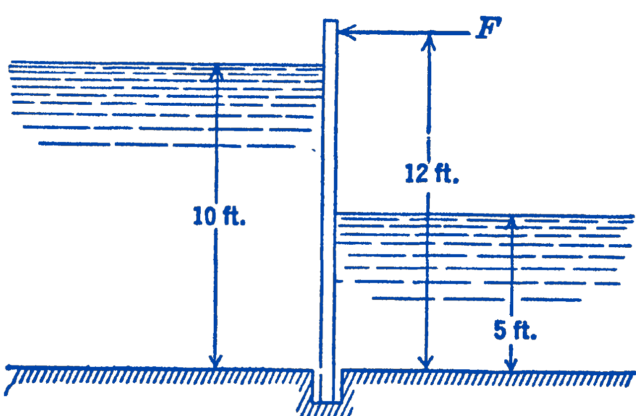
Answer
759 lb per ft
4. A cube of homogeneous material floats in water. What should be the specific weight of the material if the system is to be stable for rolling motions?
Answer
\(13.2>\gamma>49.2\ \mathrm{lb}\) per \(\mathrm{ft}^{3}\)