Planar Stress
In many engineering problems, a full three-dimensional analysis of stress is not necessary. A simple and very common example of such situations is when we deal with a planar stress system. We say a body is in planar stress when the stresses on one plane are only normal stresses. This plane is often taken perpendicular to the z-axis. In that case, the shear stresses involving the z-direction vanish: σzx=σzy=0 and the stress tensor looks like: \[ \begin{bmatrix} \sigma_{xx} & \sigma_{xy} & 0\\ \sigma_{yx} & \sigma_{yy} & 0\\ 0 & 0 & \sigma_{zz} \end{bmatrix} \] A special case of planar stress is when, in addition to shear stresses, the normal stress in the z-direction, σzz, also vanishes, we deal with what is called plane stress problems. That is, in a plane stress problem, the stress tensor looks like this: \[ \begin{bmatrix} \sigma_{xx} & \sigma_{xy} & 0\\ \sigma_{yx} & \sigma_{yy} & 0\\ 0 & 0 & 0 \end{bmatrix} \] In this case, σxx, σyy, and σxy do not vary along the thickness of the body. That is, they are functions of x and y alone, but are independent of z. 1
Another important category of planar stress problems is the so-called plane strain problems, which will be discussed later.
In the following, we often use the engineering notations for the stress components, i.e. \[ \begin{bmatrix} \sigma_x & \tau_{xy}\\ \tau_{xy} & \sigma_{y} \end{bmatrix} \]
Transformation of Stress
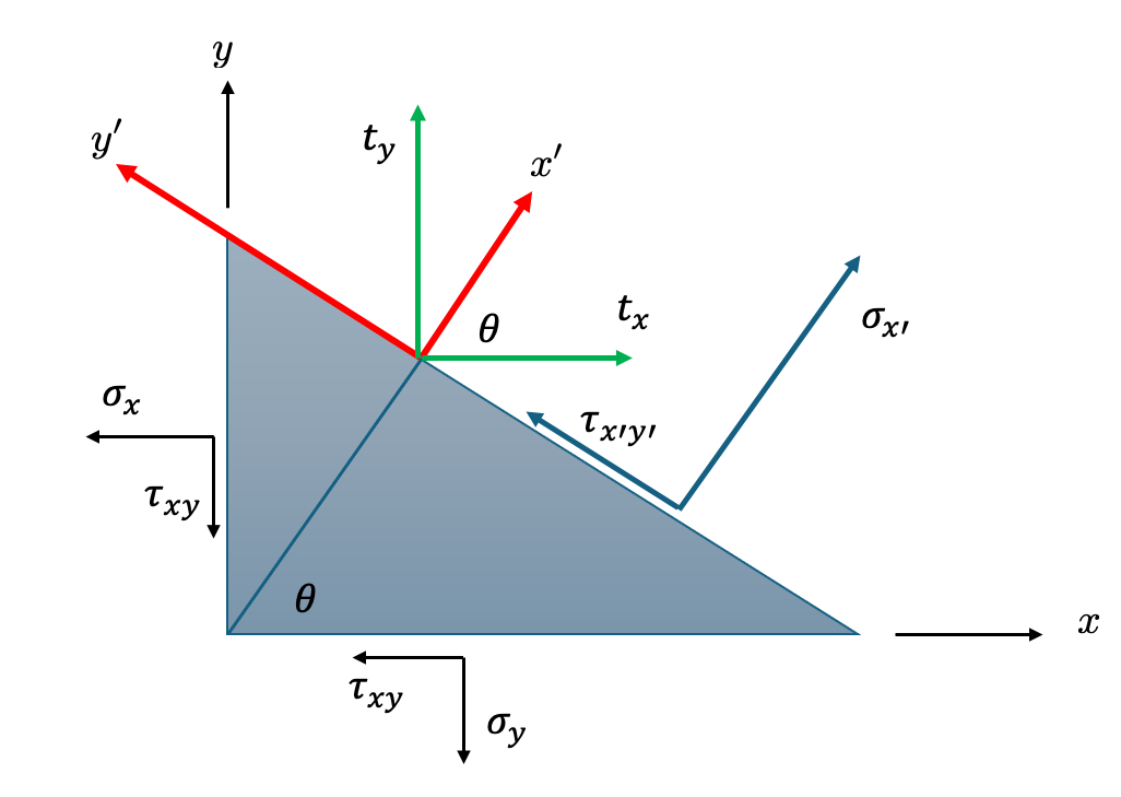
Suppose the stress components in the x-y coordinates for a plane stress problem are given. Now we want to find the components of the stress in a new coordinate system which is obtained by rotating the x- and y-axes by an angle \(\theta\).
If the length of the oblique plane is \(dl\), then the lengths of the sides the element perpendicular to the x- and y-axes are \(dl \cos\theta\) and \(dl \sin\theta\), respectively.
Let \(t_x\) and \(t_y\) be the components of the stress vector acting on the oblique plane. Then it follows from the summation of the forces along the x- and y-axes that \[ \begin{aligned} t_x dl \underbrace{h}_{\text{thickness}}&= \sigma_x\ dl\ \cos\theta\ h +\tau_{xy}\ dl\ \sin\theta\ h &&(1)\\[6pt] t_y dl\ h &= \sigma_y\ dl\ \sin\theta \ h+\tau_{xy}\ dl\ \cos \theta\ h &&(2) \end{aligned} \] where \(h\) is the thickness of the element. After simplifications, we get \[ \begin{aligned} t_x&=\sigma_x \cos \theta + \tau_{xy} \sin\theta\\ t_y&=\sigma_y \sin \theta + \tau_{xy} \cos\theta \end{aligned}\tag{3} \]

The same result can be obtained if we notice that \(\mathbf{t}\) is the stress vector on a plane whose unit normal vector is \(\begin{bmatrix}\cos\theta & \sin\theta \end{bmatrix}\): \[ \begin{aligned} \mathbf{t}&=\begin{bmatrix} \cos \theta & \sin\theta \end{bmatrix}\begin{bmatrix} \sigma_x & \tau_{xy}\\ \tau_{yx} & \sigma_y \end{bmatrix}\\ &=\begin{bmatrix} \sigma_x \cos\theta+\tau_{xy}\sin\theta & \tau_{xy}\cos\theta+\sigma_y\sin \theta \end{bmatrix} \end{aligned} \] The components of \(t_x\) and \(t_y\) in the direction of \(x'\) are \(t_x \cos \theta\) and \(t_y\sin\theta\). Their components in the y’ direction (which are the shearing components on the oblique plane) are \(-t_x\sin\theta\) and \(t_y\cos\theta\). Therefore, \[ \begin{aligned} \sigma_{x'}&=t_x \cos\theta+t_y\sin\theta\\ \tau_{x'y'}&=-t_x\sin\theta+t_y\cos\theta \end{aligned}\tag{4} \] Substituting the equations that we obtained for \(t_x\) and \(t_y\) into the above equations gives \[ \begin{aligned} \sigma_{x'}&=(\sigma_x \cos\theta+\tau_{xy}\cos\theta) \cos\theta+(\tau_{xy}\cos\theta+\sigma_y\sin \theta)\sin\theta\\ &=\sigma_x\cos^2\theta+\sigma_y\sin^2\theta+2\tau_{xy} \cos\theta \sin\theta \end{aligned} \] \[ \begin{aligned} \tau_{x'y'}&=-(\sigma_x \cos\theta+\tau_{xy}\cos\theta)\sin\theta+(\tau_{xy}\cos\theta+\sigma_y\sin \theta)\cos\theta\\ &=(\sigma_y-\sigma_x)\sin\theta\cos\theta+\tau_{xy}(\cos^2\theta-\sin^2\theta)\\ &=(\sigma_y-\sigma_x)\sin\theta\cos\theta+2\tau_{xy} \cos2\theta. \end{aligned} \] The stress \(\sigma_{y'}\) can be found from the formula for \(\sigma_{x'}\) by substituting \(\theta+\pi/2\) for \(\theta\) in that formula, since \(\sigma_{y^{\prime}}\) is orthogonal to \(\sigma_{x^{\prime}}\). \[ \sigma_{y^{\prime}}=\sigma_x \cos ^2(\theta+\pi / 2)+\sigma_y \sin ^2(\theta+\pi / 2)+2 \tau_{x y} \sin (\theta+\pi / 2) \cos (\theta+\pi / 2) \] and since \(\sin (\theta+\pi / 2)=\cos \theta\) and \(\cos (\theta+\pi / 2)=-\sin \theta\), we obtain \[ \sigma_{y^{\prime}}=\sigma_x \sin ^2 \theta+\sigma_y \cos ^2 \theta-2 \tau_{x y} \sin \theta \cos \theta \] In summary: \[ \begin{aligned} \sigma_{x^\prime} & =\sigma_x \cos ^2 \theta+\sigma_y \sin ^2 \theta+2 \tau_{x y} \sin \theta \cos \theta \\ \sigma_{y^\prime} & =\sigma_{x} \sin ^2 \theta+\sigma_y \cos ^2 \theta-2 \tau_{x y} \sin \theta \cos \theta \\ \tau_{x^\prime y^\prime} & =\left(-\sigma_x+\sigma_y\right) \sin \theta \cos \theta+\tau_{x y}\left(\cos ^2 \theta-\sin ^2 \theta\right)\end{aligned}\tag{5} \]
Since \[ \sin ^2 \theta=\frac{1}{2}(1-\cos 2 \theta), \quad \cos ^2 \theta=\frac{1}{2}(1+\cos 2 \theta), \]
we can write Eqns (5) as \[ \bbox[5px,border:1px #f2f2f2;background-color:#f2f2f2]{\begin{aligned} \sigma_{x^\prime}&=\frac{\sigma_x+\sigma_y}{2}+\frac{\sigma_x-\sigma_y}{2} \cos 2 \theta+\tau_{x y} \sin 2 \theta,\\ \sigma_{y^\prime} & =\frac{\sigma_x+\sigma_y}{2}-\frac{\sigma_x-\sigma_y}{2} \cos 2 \theta-\tau_{xy} \sin 2 \theta \\ \tau_{x' y^\prime} & =-\frac{\sigma_x-\sigma_y}{2} \sin 2 \theta+\tau_{xy} \cos 2 \theta \end{aligned}}\tag{6} \] We note that the second terms in the formulas for \(\sigma_{x'}\) and \(\sigma_y'\) and the third terms in them are the same but have opposite signs. Therefore, \[ \sigma_{x'}+\sigma_{y'}=\sigma_x+\sigma_y \tag{7} \] This means that the sum of the normal stresses on two perpendicular planes is invariant. That is, on any new coordinate system, the sum of the normal stresses is the same.
We also note that \[ \frac{d \sigma_{x'}}{d \theta}=2\tau_{x'y'}\tag{8} \] Therefore, from calculus we know that the maximum and minimum of the normal stress are achieved when the shear stress on that plane is zero \(\tau_{x'y'}=0\). \[ \tau_{x'y'}=0 \Rightarrow \tan 2\theta=\frac{2 \tau_{xy}}{\sigma_x-\sigma_y}.\tag{9} \] The two directions given by the particular values of \(\theta\) given by the above equation are called the principal directions, and the corresponding normal stresses (which are the maximum and minimum values of the normal stress on any plane) are called the principle stresses.
Since \(\tan(2\theta+\pi)=\tan(2\theta)\), if \(\theta_p\) is a solution of Eq. (9), the other one is \(\theta_p+\pi/2\). Therefore, the principal directions are perpendicular directions (or equivalently two planes that have no shear stresses are perpendicular).
If we want to find the principal stresses, we have to find \(\sin 2\theta\) and \(\cos 2\theta\) if \(\tan 2\theta\) is given by (9)., and replace the results in Eqs. (6).
Since \[ \cos^2 \alpha=\frac{1}{1+\tan^2\alpha},\quad \sin^2\alpha+\cos^2\alpha=1 \] we have \[ \begin{aligned} & \sin 2 \theta= \pm \frac{\tau_{x y}}{\left[\left(\sigma_x-\sigma_y\right)^2 / 4+\tau_{x y}^2\right]^{1 / 2}} \\ & \cos 2 \theta= \pm \frac{\left(\sigma_x-\sigma_y\right) / 2}{\left[\left(\sigma_x-\sigma_y\right)^2 / 4+\tau_{x y}^2\right]^{1 / 2}}\end{aligned} \] Substituting these values in (6) gives the principal stresses (which are the maximum and minimum values of the normal stress): \[ \bbox[5px,border:1px #f2f2f2;background-color:#f2f2f2]{\sigma_{\max,\min}=\sigma_{1,2}=\frac{\sigma_x+\sigma_y}{2} \pm\left[\left(\frac{\sigma_x-\sigma_y}{2}\right)^2+\tau_{x y}^2\right]^{1 / 2}.}\tag{10} \] To find the maximum shear stress, we have to solve \(\dfrac{d \tau_{x'y'}}{d\theta}=0\): \[ \frac{d \tau_{x^{\prime} y^{\prime}}}{d \theta}=\left(\sigma_y-\sigma_x\right) \cos 2 \theta-2 \tau_{x y} \sin 2 \theta=0 \] \[ \Rightarrow \tan 2 \theta_s=\frac{\sigma_y-\sigma_x}{2 \tau_{x y}}=-\frac{\sigma_x-\sigma_y}{2 \tau_{x y}} \tag{11} \]
Compare \(\theta_s\) to the angle \(\theta_p\) at which the principal stresses occur: \[ \bbox[5px,border:1px #f2f2f2;background-color:#f2f2f2]{\tan 2\theta_p=\frac{2 \tau_{xy}}{\sigma_x-\sigma_y}}\tag{12} \] So we see that tan 2θs is the negative reciprocal of tan 2θp, which means 2θs and 2θp are orthogonal. As a result, the directions of maximum shear and principal stress differ by 45°.
Substituting back into the shear stress transformation equation gives the maximum shear stress: \[ \bbox[background-color:#f2f2f2]{\tau_{\max }= \pm\left[\left(\frac{\sigma_x-\sigma_y}{2}\right)^2+\tau_{x y}^2\right]^{1 / 2}}\tag{13} \]
Mohr’s Circle of Stress—Two Dimensions
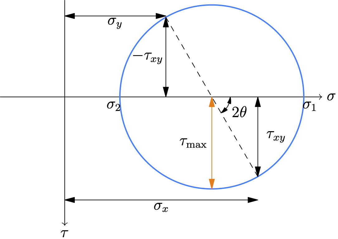
O Mohr introduced a graphical method for representing the state of stress at a point on any oblique plane. This graphical approach enables us to
- Quickly determine the principal stresses (\(\sigma_1\), \(\sigma_2\)) and their orientations.
- Find the maximum in-plane shear stress (\(\tau_{\max}\)) and its orientation.
- Solve for the stress components on any arbitrary plane without extensive calculations.
Consider the equations for \(\sigma_{x'}\) and \(\tau_{x'y'}\). Let’s isolate the trigonometric terms, by subtracting the average normal stress \(\sigma_{\text{avg}}=\dfrac{\sigma_x+\sigma_y}{2}\) from \(\sigma_{x'}\): \[ \begin{aligned} \sigma_{x^\prime}-\frac{\sigma_x+\sigma_y}{2}&=\frac{\sigma_x-\sigma_y}{2} \cos 2 \theta+\tau_{x y} \sin 2 \theta,\\ \tau_{x' y^\prime} &=-\frac{\sigma_x-\sigma_y}{2} \sin 2 \theta+\tau_{xy} \cos 2 \theta \end{aligned} \]
If we square both equations, we arrive at: \[ \left(\sigma_{x^{\prime}}-\frac{\sigma_x+\sigma_y}{2}\right)^2+\tau_{x^{\prime} y^{\prime}}^2=\left(\frac{\sigma_x-\sigma_y}{2}\right)^2+\tau_{x y}^2\tag{14} \]
By comparing the above equation with the equation of a circle with radius \(R\) and canter \((h,k)\): \[ (x-h)^2+(y-k)^2=R^2, \] we realize that (14) is the equation of a circle with center \[ (0, \sigma_{\text{avg}})=\left(0,\frac{\sigma_x+\sigma_y}{2}\right) \] and radius \[ R = \sqrt{\left( \frac{\sigma_x - \sigma_y}{2} \right)^2 + \tau_{xy}^2} \]

How to Use Mohr’s Circle
Once the circle is drawn, all possible stress states for any angle are represented on its circumference.
- Principal Stresses (σ₁ and σ₂):
- These are the points where the circle intersects the horizontal σ-axis. At these points, the shear stress is zero.
- σ₁ (Maximum Principal Stress) is the rightmost point: \(\sigma_1=C+R\) .
- σ₂ (Minimum Principal Stress) is the leftmost point: \(\sigma_2=C-R\).
- Maximum In-Plane Shear Stress (τmax):
- This is represented by the highest and lowest points on the circle.
- The value is equal to the radius: τmax = R.
- The normal stress at the points of maximum shear is the average stress, σavg.
- Stresses on an Arbitrary Plane:
- To find the stresses on a plane rotated by an angle θ counter-clockwise from the x-face on the physical element, you must rotate 2θ counter-clockwise from the reference line CX on Mohr’s Circle.
- The coordinates of this new point on the circle give you the new stress state (σx’, τx’y’).
Key Rule: A rotation of θ on the physical stress element corresponds to a rotation of 2θ in the same direction on Mohr’s Circle.
- The statement that in-plane stresses are independent of the z-coordinate is a direct result of the shear stresses σxz and σyz being zero. This can be proven by combining the equations of equilibrium with the material’s stress-strain laws. However, for this model to be physically valid, the object’s z-dimension must be very small compared to its other dimensions.↩︎