The stiffness matrix of the entire structure (the “global” stiffness matrix) is formed by combining the stiffness matrices of each individual element. This process is called assembly. The fundamental idea is that the total stiffness at any given degree of freedom is the sum of the stiffness contributions from all elements connected to that degree of freedom.
We can understand this intuitively by considering a simple system of two springs in series.
Example: Two Springs in Series
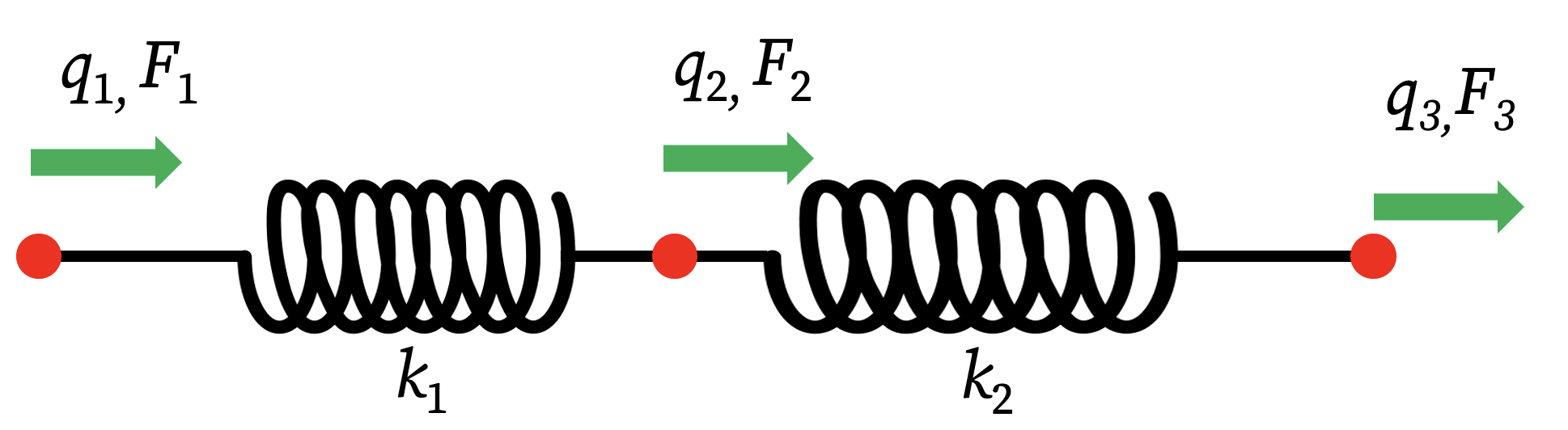
Consider a system with three nodes and two springs connecting them, as shown in the notes. There are three nodal displacements (degrees of freedom) q₁, q₂, q₃ and three corresponding nodal forces F₁, F₂, F₃.
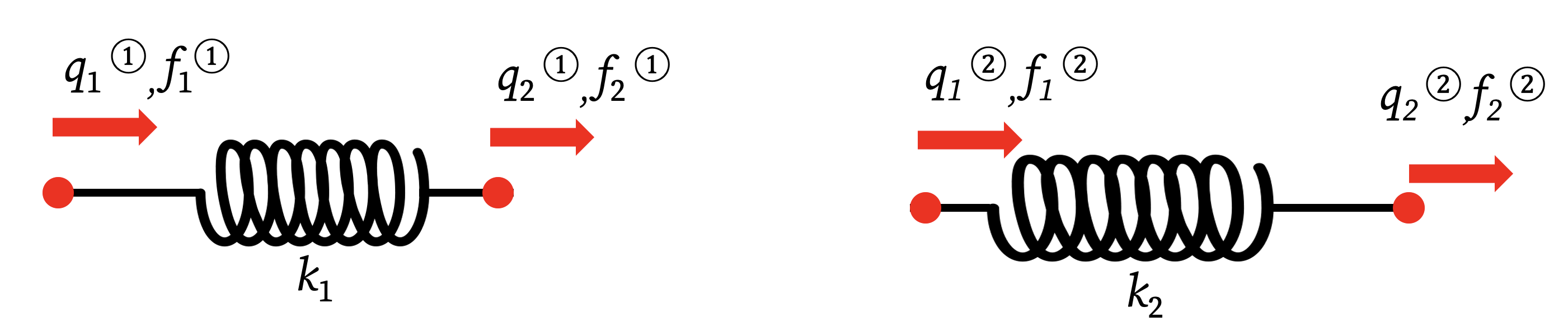
Step 1: Define Element Stiffness Matrices We first write the stiffness relationship for each spring (element) separately. Each spring is a 1D element with two nodes.
- For Spring 1 (stiffness k₁): The local forces
f₁⁽¹⁾andf₂⁽¹⁾are related to the local displacementsq₁⁽¹⁾andq₂⁽¹⁾. \[ \begin{bmatrix} f_1^{(1)} \\ f_2^{(1)} \end{bmatrix} = \begin{bmatrix} k_1 & -k_1 \\ -k_1 & k_1 \end{bmatrix} \begin{bmatrix} q_1^{(1)} \\ q_2^{(1)} \end{bmatrix} \] - For Spring 2 (stiffness k₂): Similarly, for the second spring: \[ \begin{bmatrix} f_1^{(2)} \\ f_2^{(2)} \end{bmatrix} = \begin{bmatrix} k_2 & -k_2 \\ -k_2 & k_2 \end{bmatrix} \begin{bmatrix} q_1^{(2)} \\ q_2^{(2)} \end{bmatrix} \]
Step 2: Establish Compatibility and Equilibrium We connect the individual elements by enforcing two conditions:
- Displacement Compatibility: We relate the element’s local nodal displacements to the structure’s global nodal displacements.
q₁⁽¹⁾ = q₁q₂⁽¹⁾ = q₂andq₁⁽²⁾ = q₂(The middle node is shared)q₂⁽²⁾ = q₃
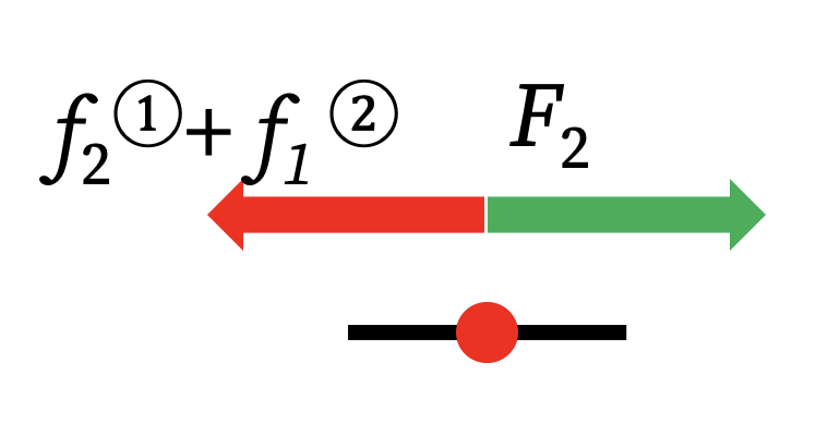
- Force Equilibrium: The external force at each global node must be equal to the sum of the internal forces from all elements connected to that node.
F₁ = f₁⁽¹⁾F₂ = f₂⁽¹⁾ + f₁⁽²⁾(The force at the middle node is the sum of forces from both springs)F₃ = f₂⁽²⁾
Step 3: Assemble the Global Stiffness Matrix We now build the global system F = Kq by substituting the element equations into the equilibrium equations.
- Row 1 (Force F₁):
F₁ = f₁⁽¹⁾ = k₁q₁⁽¹⁾ - k₁q₂⁽¹⁾ = k₁q₁ - k₁q₂ - Row 2 (Force F₂): This is the key step showing superposition.
F₂ = f₂⁽¹⁾ + f₁⁽²⁾ = (-k₁q₁⁽¹⁾ + k₁q₂⁽¹⁾) + (k₂q₁⁽²⁾ - k₂q₂⁽²⁾)Substituting the global displacements:F₂ = (-k₁q₁ + k₁q₂) + (k₂q₂ - k₂q₃) = -k₁q₁ + (k₁ + k₂)q₂ - k₂q₃ - Row 3 (Force F₃):
F₃ = f₂⁽²⁾ = -k₂q₁⁽²⁾ + k₂q₂⁽²⁾ = -k₂q₂ + k₂q₃
Writing these three equations in matrix form gives us the assembled global stiffness matrix for the entire structure:
\[ \begin{bmatrix} F_1 \\ F_2 \\ F_3 \end{bmatrix} = \begin{bmatrix} k_1 & -k_1 & 0 \\ -k_1 & k_1+k_2 & -k_2 \\ 0 & -k_2 & k_2 \end{bmatrix} \begin{bmatrix} q_1 \\ q_2 \\ q_3 \end{bmatrix} \]
Notice how the K₂₂ term (k₁ + k₂) is the sum of the stiffnesses of the two elements connected to that degree of freedom. This “direct superposition” is the essence of the assembly process in the Finite Element Method.